
A new type of intelligent commutation switch and method for distribution station area

A non-contact switch and user technology, applied in the power field, can solve the problems of increased loss of distribution transformers and load lines, unbalanced load between three phases, and increased A-phase load, etc., to reduce switching transient effects, no conduction Through-voltage drop and loss, the effect of eliminating the need for heat sinks

Active Publication Date: 2019-01-25
江苏首捷智能设备有限公司
View PDF5 Cites 0 Cited by
  • Summary
  • Abstract
  • Description
  • Claims
  • Application Information

AI Technical Summary

Problems solved by technology

Since the electrical equipment of each user is different, it is very easy to cause unbalanced load among the three phases.
For example, when too many high-load (high-power) users access phase A, the load of phase A will increase sharply, and the load of phase B or phase C will be relatively light due to fewer users accessing, thus causing A, Unbalance between B and C three phases
The unbalanced three-phase load will cause a series of hazards such as increased loss of distribution transformers and load lines, decreased quality of supply voltage, decreased power conversion efficiency, and increased operating temperature of distribution transformers.
However, in this commutation process, the opening and closing timing of the mechanical contact switch is relatively random, which has a large impact on the power receiving user and the switch, and arcs will be generated during the opening and closing process, and there is a short-term gap during the switching period. Power supply interruption, this interruption is unacceptable in some important power supply occasions (such as hospitals, etc.)

Method used


Image

  • A new type of intelligent commutation switch and method for distribution station area
  • A new type of intelligent commutation switch and method for distribution station area
  • A new type of intelligent commutation switch and method for distribution station area

Examples


Embodiment 1

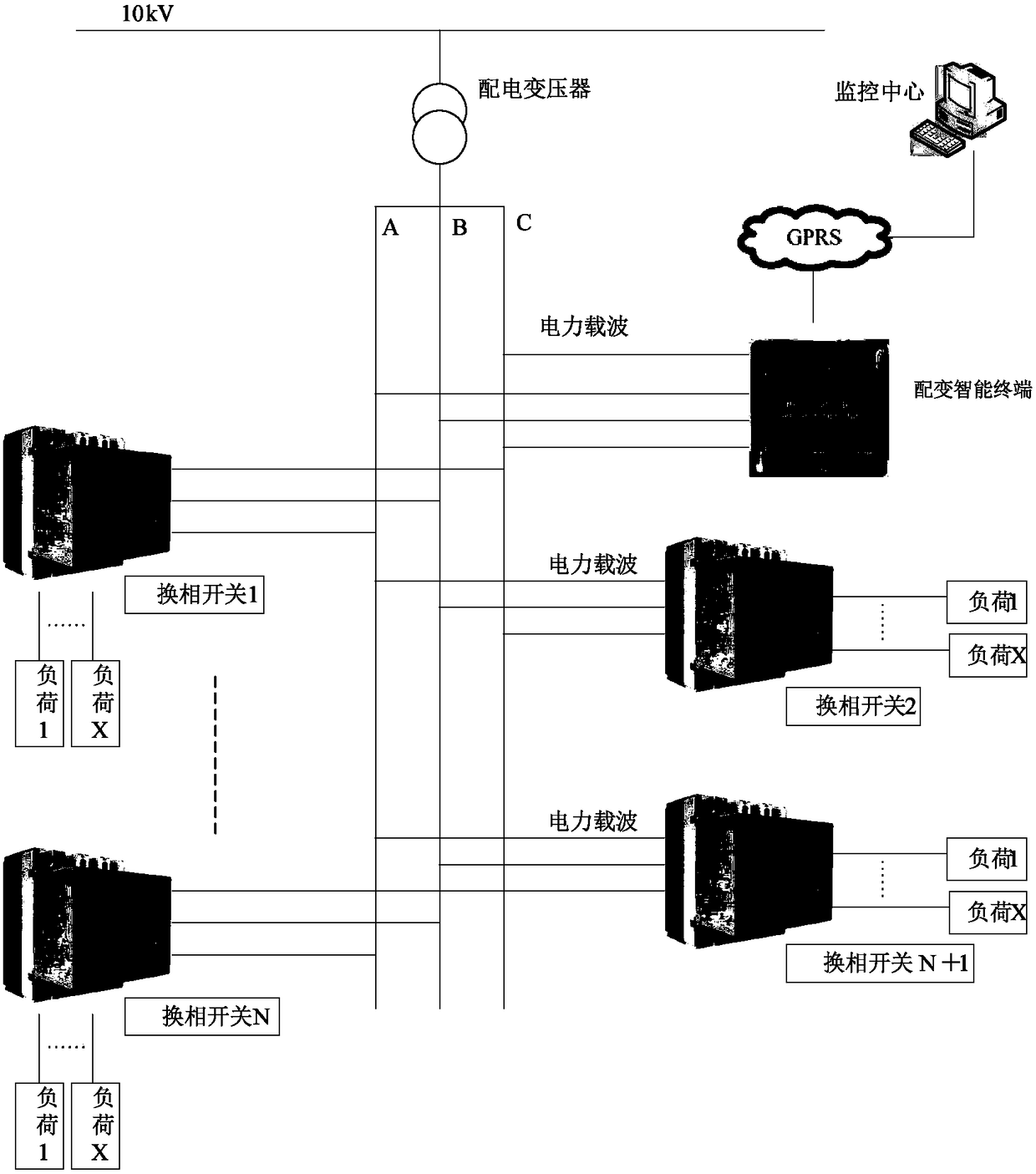
[0016] see figure 2 First, the overall structure of the present invention is introduced. In the present invention, the intelligent management terminal is used to detect the loads of each phase of the three-phase AC buses A, B, and C of the distribution transformer, and the electric quantity measuring devices such as ammeters and voltmeters measure the voltages of the three-phase AC buses A, B, and C, The current and other parameters are transmitted to the intelligent management terminal, and the intelligent management terminal communicates with the phase change devices installed in various places. A commutation command is sent to the corresponding device, and the commutation device executes the commutation operation after receiving the commutation command. The intelligent management terminal can also communicate with the monitoring center through, for example, GPRS, so as to send the state of the intelligent management terminal to the monitoring center, or receive the commut...

Embodiment 2

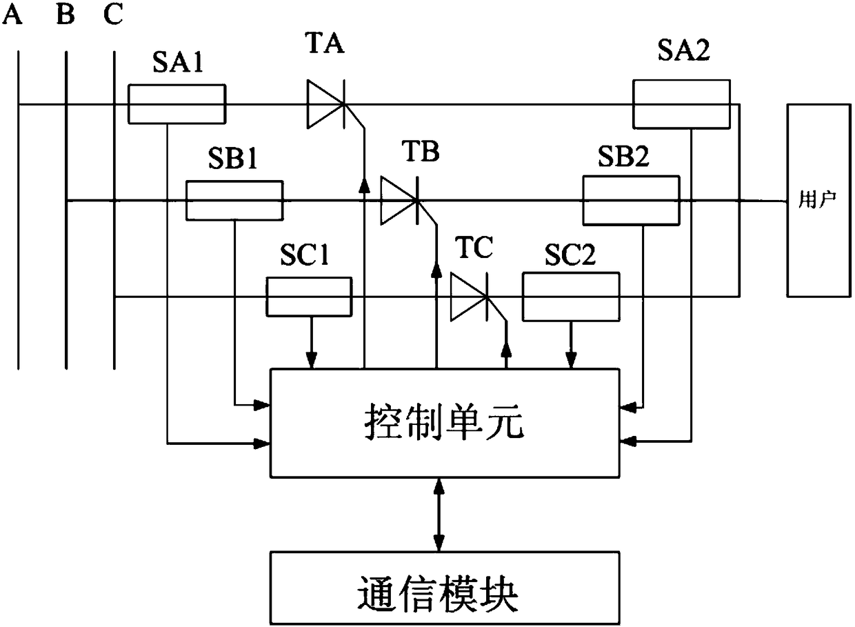
[0029] see Figure 6 Correspondingly, the present invention also discloses a phase commutation method, a phase commutation method, comprising the following steps: S100: receiving a phase commutation instruction for switching from the current phase to the target phase; S200: obtaining the current period T1 of the current phase where the user is located and the voltage cycle T2 of the target phase to be connected by the user; S300: connect the user to the three-phase AC bus through a plurality of non-contact switch units; S400: pre-store the guides of the plurality of non-contact switch units On-time; S500: At the initial moment t0 of receiving the phase-change instruction, calculate the current-phase off time according to the current period T1 of the current phase and the pre-stored on-time of the non-contact switch unit of the current phase The trigger moment tc makes the non-contact switch unit of the current phase be turned off at the time t1 when the current phase current c...


PUM


Abstract

The invention discloses a phase change device, which comprises a communication module, a period measurement module, multiple contactless switch units, a storage module and a central processing module, wherein the communication module is used for receiving a phase change instruction for changing from the current phase to a target phase; the period measurement module is used for acquiring a current period T1 of the current phase of the user and a voltage period T2 of the target phase to which the user needs to be accessed; the multiple contactless switch units are used for connecting the user with a three-phase AC bus via the multiple contactless switch units; the storage module is used for pre-storing conduction time of the multiple contactless switch units; and the central processing module is used for changing the user from the current phase to the target phase. Thus, three-phase load balanced management can be realized, and a distribution transformer can be well protected.

Description

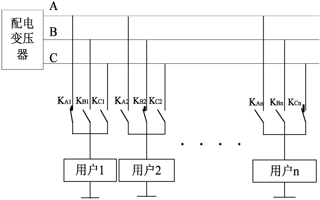
technical field [0001] In general, the present invention belongs to the field of electric power, and in particular relates to a phase commutation device and method. Background technique [0002] There are many power users in my country's distribution network and their locations are scattered, and there are a large number of single-phase loads with unbalanced spatio-temporal distribution, resulting in varying degrees of unbalanced three-phase loads in most distribution areas. We refer to the area powered by the distribution transformer as the distribution station area, such as figure 1 As shown, the distribution transformer transmits power through the three-phase AC buses A, B, and C. User 1, user 2...User n are respectively connected to the three-phase AC bus. Taking user 1 as an example, user 1 is connected to the three-phase AC bus through a mechanical contact. The point switch KA1 is connected to phase A, connected to phase B through KB1, and connected to phase C through...

Claims


Application Information

Patent Timeline
Patent Type & Authority Patents(China)
IPC IPC(8): H02J3/26
CPCY02E40/50
Inventor 于建东
Owner 江苏首捷智能设备有限公司
Learn More