Solid-state relay of contactless switch

A solid state relay, non-contact switch technology, applied in electronic switches, circuits, electrical components, etc., can solve the problems of mechanical fatigue life, low output signal sensitivity, etc.

Pending Publication Date: 2022-03-25
浙江正泰汽车科技有限公司
View PDF0 Cites 0 Cited by
  • Summary
  • Abstract
  • Description
  • Claims
  • Application Information

AI Technical Summary

Problems solved by technology

[0003] In the prior art, the electrical contacts of the relay usually use dynamic and static contacts to cooperate to form a contact switch, so as to be used as a switching device for the circuit, but at least the following defects exist: 1. A moving contact is required for switching between the moving and static contacts. Perform high-frequency movement, resulting in mechanical fatigue and short life; 2. Not suitable for harsh environments with high mechanical shock and high-frequency vibration; 3. The sensitivity of the output signal is relatively low, and it is necessary to increase the mechanical electromagnetic driver or actuator buffer

Method used


Image

  • Solid-state relay of contactless switch
  • Solid-state relay of contactless switch

Examples


Embodiment Construction

[0010] The specific embodiment of the present invention is described in detail below in conjunction with accompanying drawing:

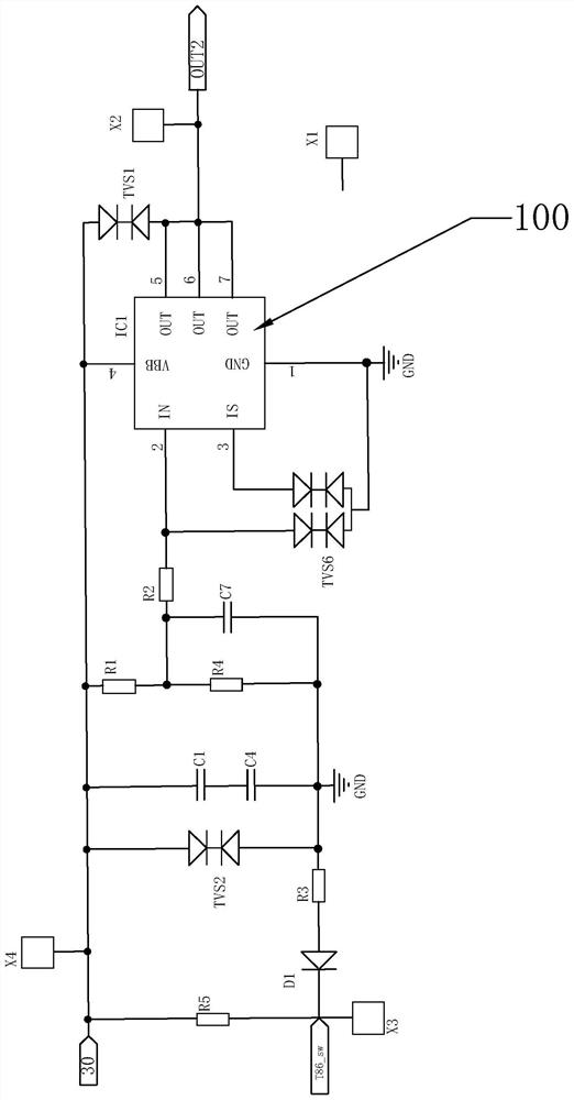
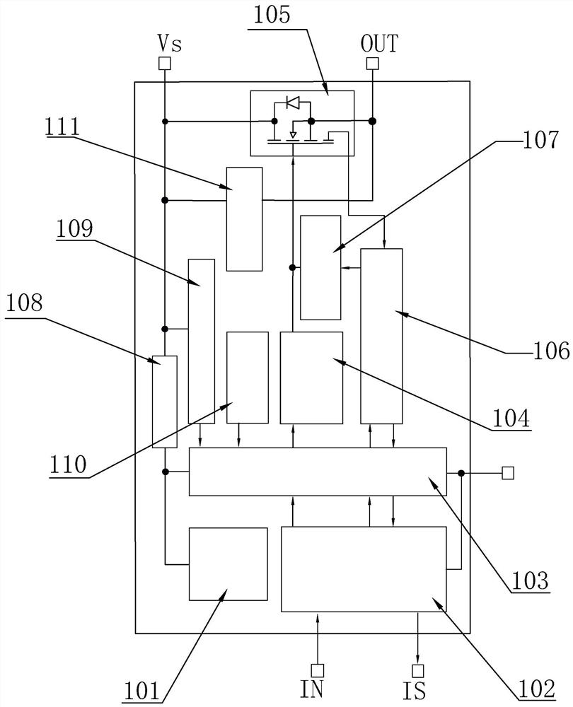
[0011] The disclosure of the present invention relates to a solid-state relay of a non-contact switch. In the implementation case of the present invention, it includes two input terminals and one output terminal, and also includes a resistor R1, a resistor R2, a resistor R3, a resistor R4, a resistor R5, and a capacitor C1 , capacitor C4, capacitor C7, diode D1, transient diode TVS1, transient diode TVS2, transient diode TVS6 and MOS control unit 100, capacitor C1 and capacitor C4 are connected in series to form a capacitor group, resistor R5, transient diode TVS2 and The capacitor groups are arranged in parallel in turn, the cathode of the diode D1 is electrically connected to R5, the anode of the diode D1 is electrically connected to one end of the resistor R3, the other end of the resistor R3 is electrically connected to the transient diode TVS2, a...


PUM


Abstract

A capacitor C1 and a capacitor C4 are connected in series to form a capacitor bank, a resistor R5, a transient diode TVS2 and the capacitor bank are sequentially arranged in parallel, the negative electrode of a diode D1 is electrically connected with the R5, the positive electrode of the diode D1 is electrically connected with one end of a resistor R3, the other end of the resistor R3 is electrically connected with the transient diode TVS2, and the other end of the resistor R3 is electrically connected with the capacitor bank. One end of the resistor R2 is connected between the resistor R1 and the resistor R4, the other end of the resistor R2 is electrically connected to an input pin IN of the MOS control unit, the transient diode TVS6 is connected between the input pin IN and an output pin IS of the MOS control unit and is grounded, one end of the transient diode TVS1 is electrically connected with a base power supply wiring pin VBB of the MOS control unit, and the other end of the transient diode TVS2 is electrically connected with a base power supply wiring pin VBB of the MOS control unit. The MOS control unit is used for replacing a contact switch for control, the service life is long, the circuit is suitable for high-punching and vibration working environments, and the sensitivity is high.

Description

technical field [0001] The invention relates to the technical field of circuit breakers, in particular to a solid-state relay of a non-contact switch. Background technique [0002] Relay (English name: relay) is an electrical control device, which is an electrical appliance that causes the controlled quantity to undergo a predetermined step change in the electrical output circuit when the change of the input quantity (excitation quantity) meets the specified requirements. It has an interactive relationship between the control system (also known as the input loop) and the controlled system (also known as the output loop). Usually used in automatic control circuits, it is actually an "automatic switch" that uses a small current to control the operation of a large current. Therefore, it plays the role of automatic adjustment, safety protection, and conversion circuit in the circuit. [0003] In the prior art, the electrical contacts of the relay usually use dynamic and static...

Claims


Application Information

Patent Timeline
IPC IPC(8): H03K17/687H03K17/0812
CPCH03K17/687H03K17/08122H03K2017/0806
Inventor 汪成马高忠杨涛詹承杰谷芬芬
Owner 浙江正泰汽车科技有限公司
Why Eureka
Try Eureka