Method for operating an integrated MEMS microphone device and integrated MEMS microphone device

a microphone device and microphone technology, applied in the field of integrated mems microphone devices, can solve the problems of fast heating or cooling of air, audible transients, and power consumption of environmental sensors that can modulate the temperature inside the cavity, so as to reduce power consumption, and reduce the effect of transients

Active Publication Date: 2021-03-23
AMS AG
View PDF7 Cites 0 Cited by
  • Summary
  • Abstract
  • Description
  • Claims
  • Application Information

AI Technical Summary

Benefits of technology

[0016]The following relates an improved concept for a method for operating an integrated MEMS microphone device and, further, to an integrated MEMS microphone device implementing the method. The concept employs a thermal decoupling circuit to gradually adjust a heat dissipation into the cavity during a transition phase to reduce the effect of transients in an audio signal recorded by the integrated MEMS microphone. In fact, “click” or “pop” noise can be reduced or eliminated from the audio signal.
[0023]The proposed method, including gradually adjusting a heat dissipation into the cavity during the transition phase by means of the thermal decoupling circuit, reduces the effect of transients in the audio signal recorded by the integrated MEMS microphone. In fact, “click” or “pop” noise can be reduced or eliminated from the audio signal. Furthermore, the proposed concept allows for rather simple and small amount of additional circuitry to implement the method into an integrated MEMS microphone device. In some embodiments in may even be possible to use the environmental sensor itself or a part thereof as the thermal decoupling circuit. The proposed concept may not limit additional sensor functions or limit power consumption, for example of the environmental sensor.
[0041]The proposed integrated MEMS microphone device, including the thermal decoupling circuit configured to gradually dissipate power in the transition phase, reduces the effect of transients in the audio signal to be recorded. In fact, “click” or “pop” noise can be reduced or eliminated from the audio signal. Furthermore, the proposed concept allows for rather simple and small amount of additional circuitry to be implemented into the integrated MEMS microphone device. In some embodiments in may even be possible to use the environmental sensor or a part thereof as the thermal decoupling circuit. The proposed concept may not limit additional sensor functions or limit power consumption, for example of the environmental sensor.

Problems solved by technology

This results in fast heating or cooling of the air which is present in the rather small back volume of the interior cavity, respectively.
Thus, power consumption of an environmental sensor can modulate temperature inside the cavity.
Thus, due to the small volume even a small change in temperature can result in an audible transient.
For example, reducing power typically also reduces circuit performance.
Keeping the circuits on even if it is not needed increases the power consumption.

Method used


Image

  • Method for operating an integrated MEMS microphone device and integrated MEMS microphone device
  • Method for operating an integrated MEMS microphone device and integrated MEMS microphone device
  • Method for operating an integrated MEMS microphone device and integrated MEMS microphone device

Examples


Embodiment Construction

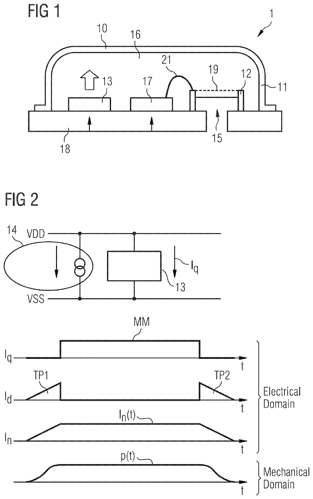
[0054]FIG. 1 shows an exemplary embodiment of an integrated microelectromechanical systems, MEMS, microphone device (MEMS microphone for short). The MEMS microphone device 1 comprises a package housing 10, a lid 11, an integrated MEMS microphone die 12, an integrated circuit die 17, at least one environmental sensor 13 and a thermal decoupling circuit 14.

[0055]The package housing 10 has a sound hole 15 which is arranged in and through the housing, leaving the housing open to its environment. For example, the sound hole communicates sound from outside the package housing to an interior of the package housing. In fact, an interior cavity 16 is defined by a lid 11 which is mounted to a substrate 18 of the package housing. The lid 11 encapsulated the interior of the package housing and thereby forms the interior cavity.

[0056]The integrated MEMS microphone die 12 is mounted on the substrate and resides inside the interior cavity. The MEMS microphone die comprises a movable membrane 19, e...


PUM


Abstract

A method for operating an integrated MEMS microphone device is proposed. The integrated MEMS microphone device comprises a package housing enclosing an interior cavity, wherein an integrated MEMS microphone die with a movable membrane, at least one environmental sensor and a thermal decoupling circuit are arranged inside the cavity. The method comprising the steps of repeatedly operating the environmental sensor in a measurement mode and activating the thermal decoupling circuit for a transition phase preceding and / or succeeding the measurement mode of the environmental sensor. During the transition phase a heat dissipation into the cavity is gradually adjusted.

Description

CROSS-REFERENCE TO RELATED APPLICATIONS[0001]The present application is the national stage entry of International Patent Application No. PCT / EP2018 / 067950, filed on Jul. 3, 2018, which claims the benefit of priority of European Patent Application No. 17181409.8, filed on Jul. 14, 2017, all of which are hereby incorporated by reference in their entirety for all purposes.[0002]This invention relates to a method for operating an integrated MEMS microphone device and, further, to an integrated MEMS microphone device.BACKGROUND OF THE INVENTION[0003]Microelectromechanical systems, MEMS, microphones play a key role in many audio applications. MEMS microphones are highly integrated components using sophisticated package design and combine small size, high sound quality, reliability and affordability. Ongoing efforts in sensor technology seek to further integrate additional sensor concepts into single integrated MEMS microphone devices. For example, a MEMS microphone can be complemented wit...

Claims


Application Information

Patent Timeline
Patent Type & Authority Patents(United States)
IPC IPC(8): H04R1/08B81B7/00H04R1/02
CPCH04R1/08B81B7/0032B81B7/0087B81B7/0093H04R1/021B81B2201/0257H04R2201/003H04R3/007H04R2410/03
Inventor NISHIMURA, NAOAKI
Owner AMS AG
Why Eureka
Try Eureka