Transmission apparatus

a technology of transient response and amplifier, applied in the field of transmission techniques, can solve problems such as the inaccurate variation of the signal, and achieve the effect of reducing the effect of the transient response generated when the amplifier is turned from off to on

Active Publication Date: 2010-10-14
KYOCERA CORP
View PDF2 Cites 0 Cited by
  • Summary
  • Abstract
  • Description
  • Claims
  • Application Information

AI Technical Summary

Benefits of technology

[0009]According to the present invention, the effects of a transient response that is generated when an amplifier is turned from off to on can be reduced.

Problems solved by technology

In the transmission side of such a system (hereinafter, referred to as a “transmission apparatus”), there is a possibility that the accuracy of the variations becomes worse as the output level of a transmission wave changes.

Method used


Image

  • Transmission apparatus
  • Transmission apparatus
  • Transmission apparatus

Examples


Embodiment Construction

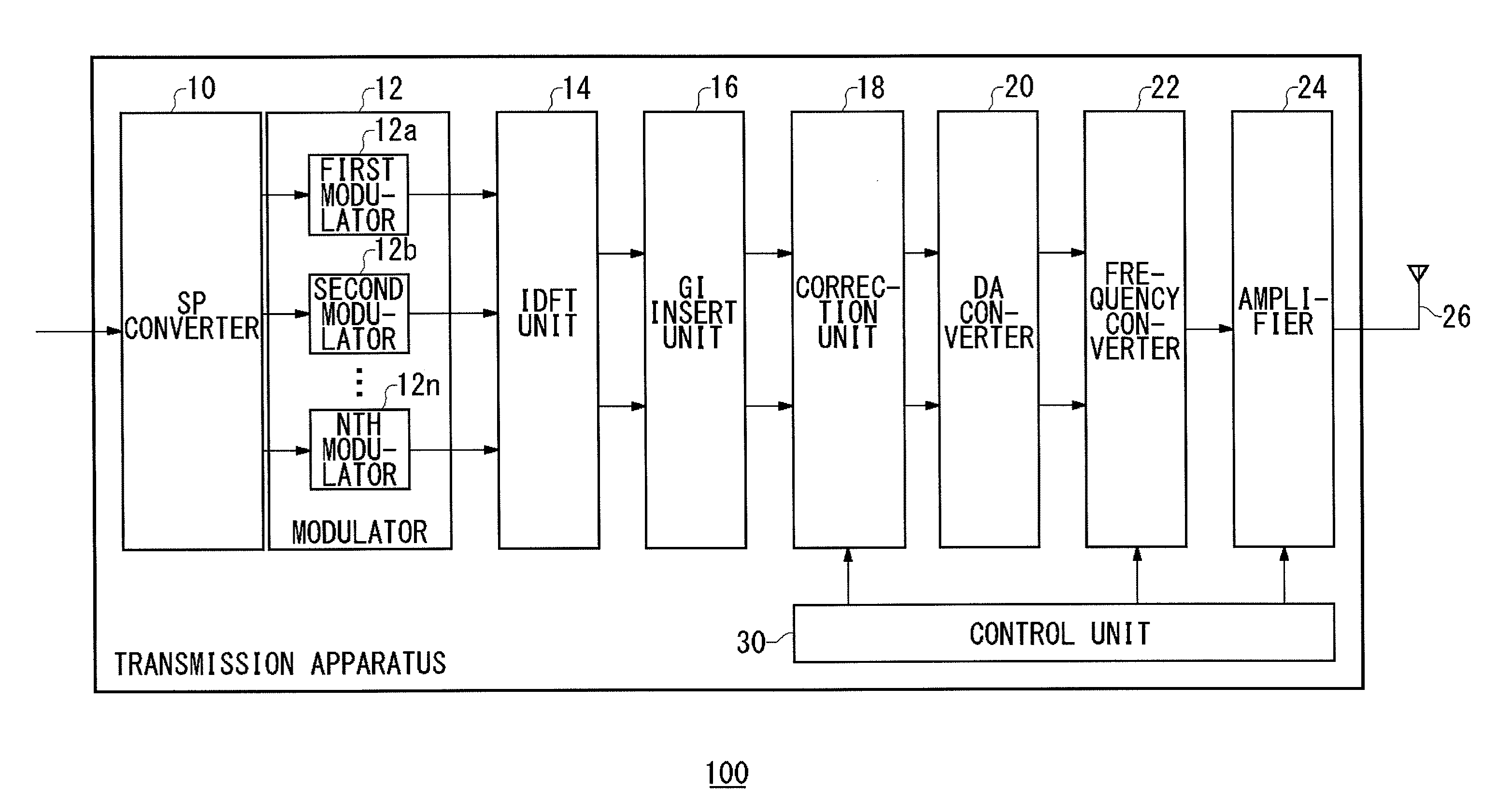
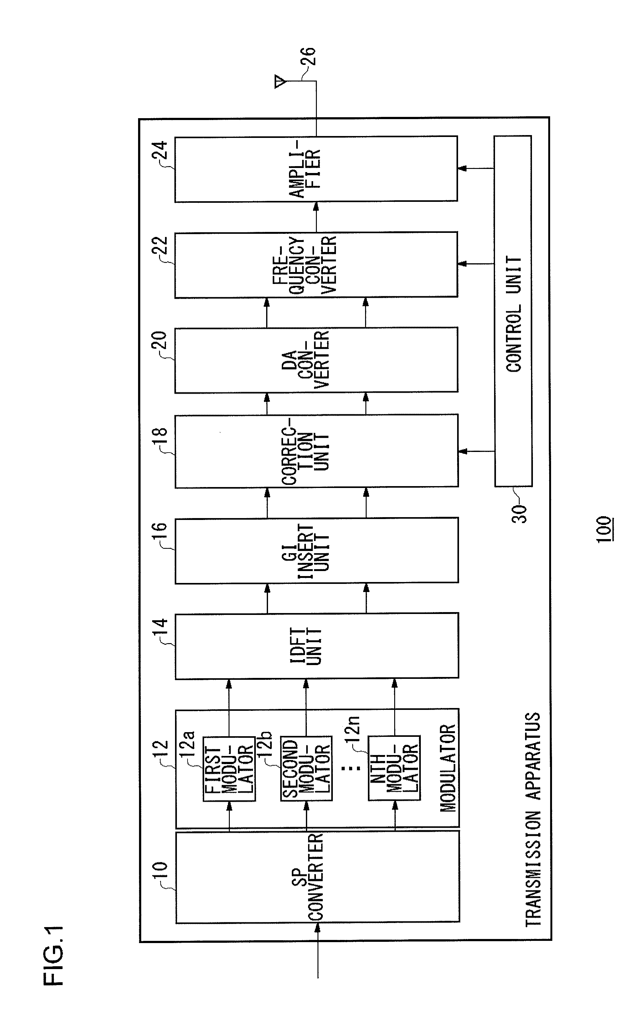
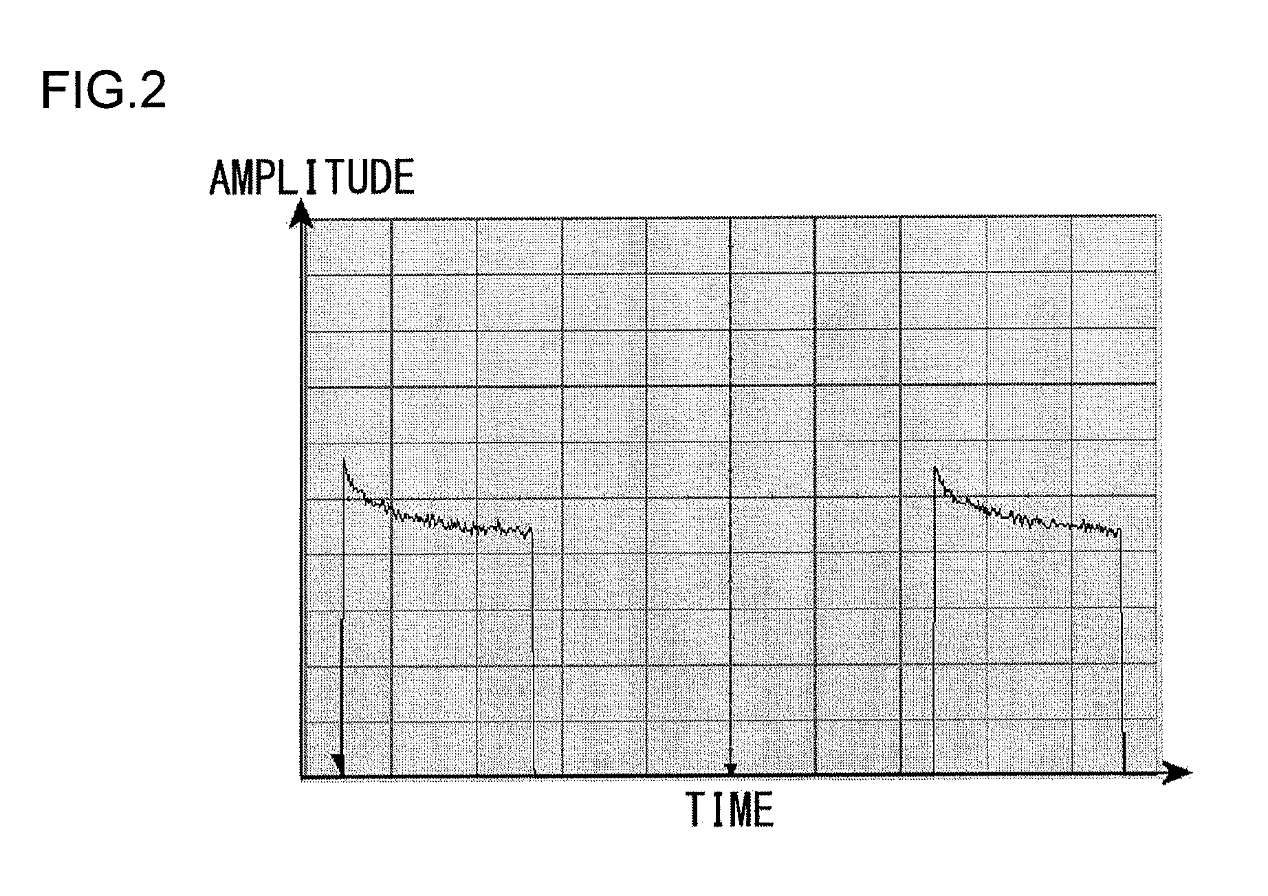
[0043]A brief description is now given before focusing on specific features of the present invention. Exemplary embodiments of the present invention relate to a communication system, just as a second generation cordless telephone system, that is adaptable to the TDMA scheme and the TDD scheme. Thus, frames in a communication system are formed by time division multiplexing of multiple time slots. Attention is now focused particularly on a transmission apparatus. The transmission apparatus is provided with a power amplifier, and the power amplifier is turned on at the header timing of the time slot in which a data signal is arranged (hereinafter, a data signal arranged in a time slot is also referred to as a “packet signal”). Therefore, a transient response is generated immediately after the amplifier is turned on, in other words, a transient response is generated at the header part of the time slot. As a result, the EVM becomes larger in the header part. In order to suppress the incr...


PUM


Abstract

A modulator modulates the packet data signal. A correction unit 18 adjusts the amplitude component of the modulated data signal. An amplifier amplifies the adjusted data signal and outputs the data signal. A control unit controls the operation of the amplifier. The control unit turns on the operation of the amplifier at the header timing of a packet. The amplifier generates a transient response in the header part of the packet when the amplifier is turned on. In accordance with the inverse characteristic of the transient response generated in the amplifier, the correction unit adjusts the amplitude component of the modulated data signal.

Description

TECHNICAL FIELD[0001]The present invention relates to transmission techniques and particularly to a transmission apparatus that transmits amplified signals.BACKGROUND ART[0002]In recent years, wireless apparatuses have been developed such as mobile phones that use a scheme such as FDMA (Frequency Division Multiple Access), TDMA (Time Division Multiple Access) or CDMA (Code Division Multiple Access) for effective utilization of frequencies. Particularly in TDMA systems and TDD systems, transmission and reception are conducted on a time slot-by-time slot basis since multiplex or bidirectional communication is performed in a time-multiplexed manner. In the transmission side of such a system (hereinafter, referred to as a “transmission apparatus”), there is a possibility that the accuracy of the variations becomes worse as the output level of a transmission wave changes. For this reason, the output level of a transmission wave is preferably stable (for example, see patent document 1).[0...

Claims


Application Information

Patent Timeline
Patent Type & Authority Applications(United States)
IPC IPC(8): H04L27/04H04L12/43
CPCH03F1/0261H03F1/32H03F3/24H04L27/368H04B1/0475H04L5/0007H04L27/2626H03F2200/336
Inventor NARITA, MASAHIRO
Owner KYOCERA CORP
Why Eureka
Try Eureka