Detachable and assembled arc-shaped precise positioning equipment
A precise positioning and arc-shaped technology, applied in the field of medical devices, can solve problems such as structural damage, increased damage, and inaccuracy
- Summary
- Abstract
- Description
- Claims
- Application Information
AI Technical Summary
Problems solved by technology
Method used
Image
Examples
Embodiment 1
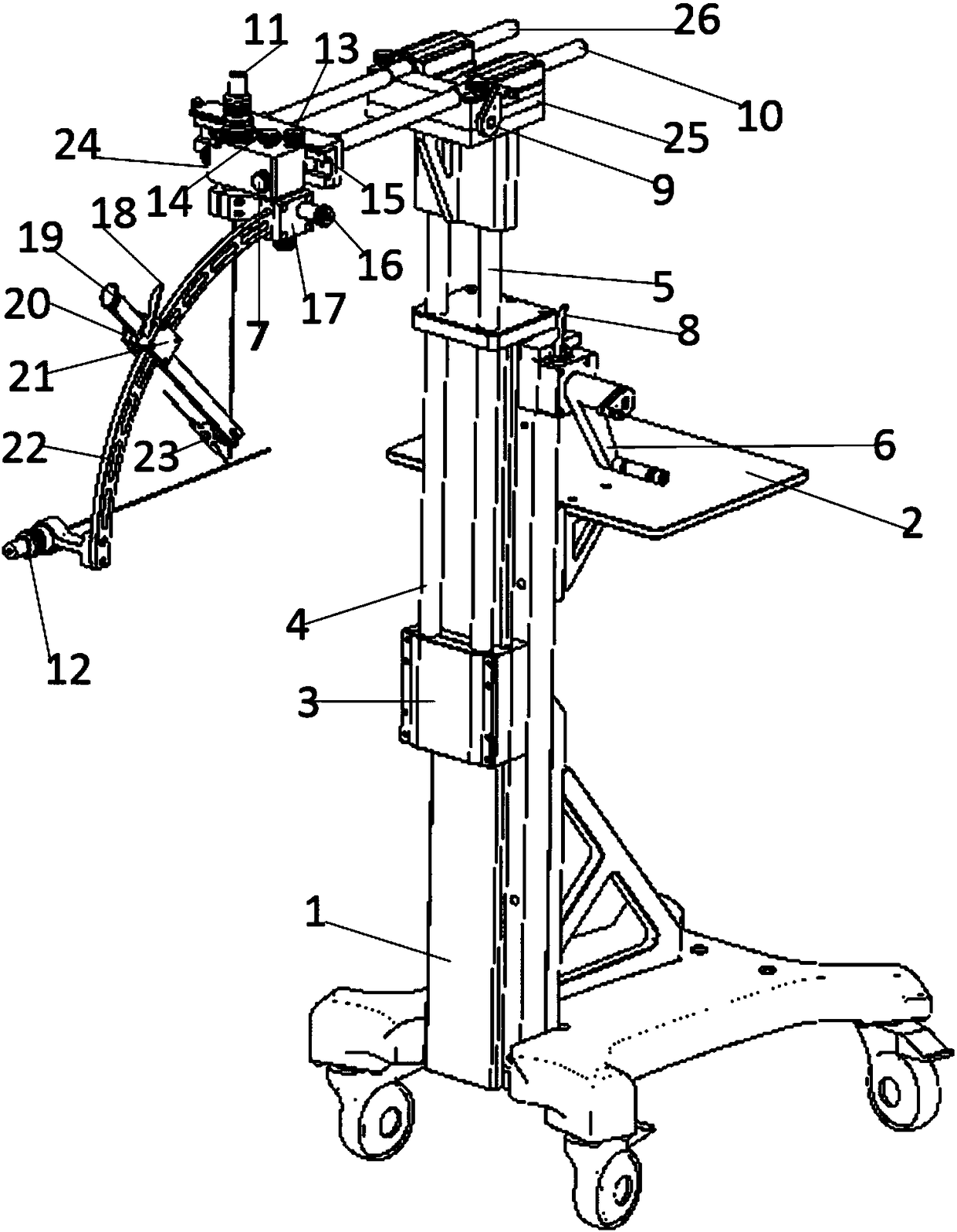
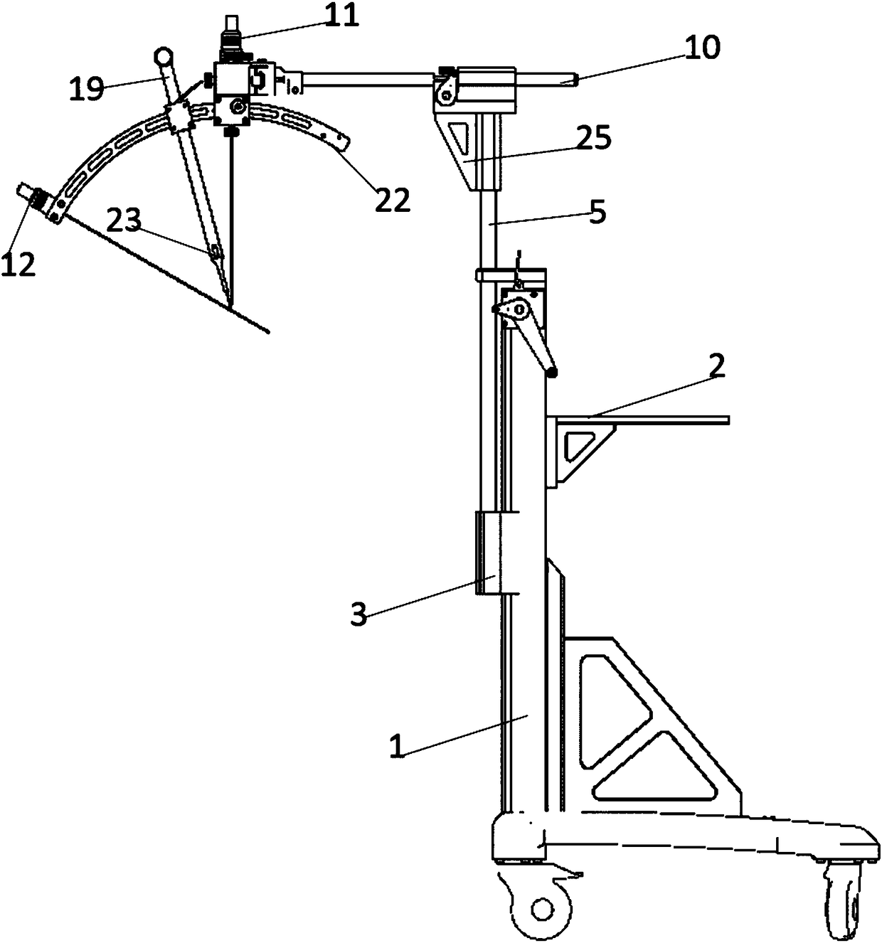
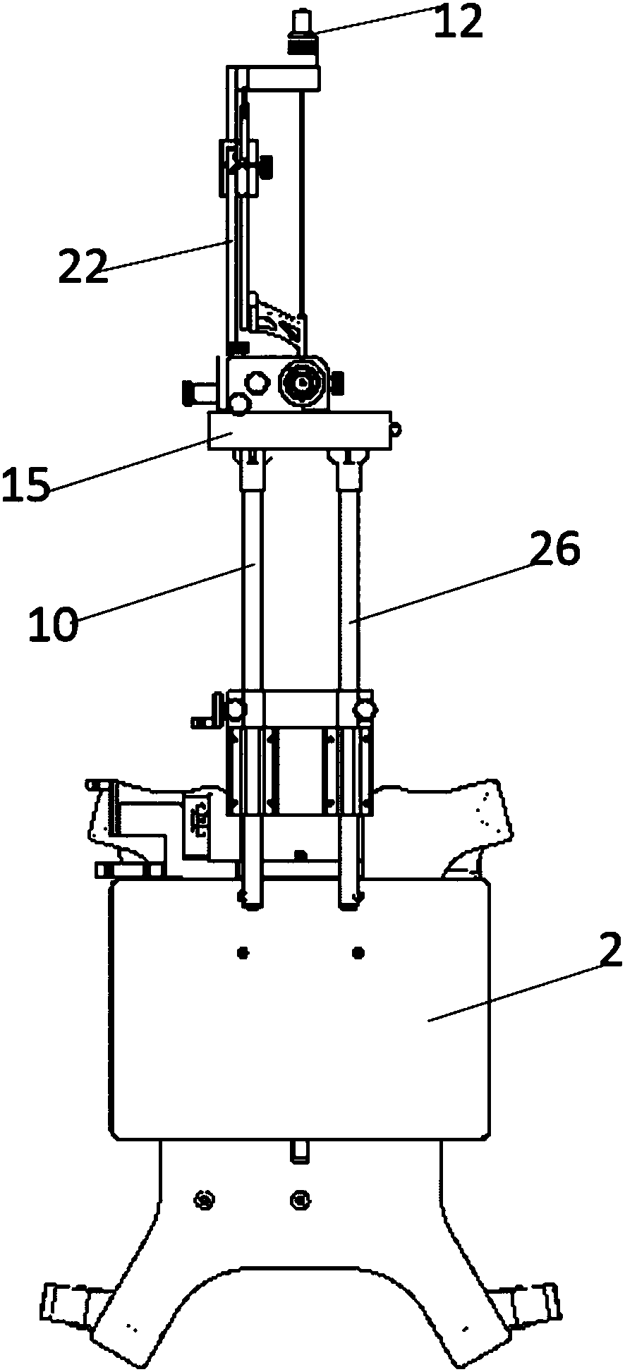
[0079] like Figure 1-3 As shown, a detachable and assembled arc-shaped precise positioning device includes a support unit, a three-dimensional adjustment unit and a guide positioning unit.
[0080] Its support unit includes an L-shaped base composed of a base and a vertical guide rail 1 perpendicular to the base. The base is provided with rollers and a brake device that can fix the ground, which is convenient for moving and fixing the detachable and assembled arc-shaped precise positioning equipment. On the vertical guide rail 1, a storage table 2 can be installed horizontally, which is used to place a spare instrument box during the operation, and the actual size of the storage table is adjusted according to the actual situation of the operation.
[0081] In this embodiment, the three-dimensional adjustment unit includes a lift adjustment unit and a horizontal adjustment unit.
[0082] The lifting adjustment unit includes a first fixed block 3 arranged on the vertical guide...
Embodiment 2
[0106] like Figure 7 As shown, the difference from Embodiment 1 is that there are two locators, namely a vertical locator 11 and a horizontal locator 12, the horizontal locator 12 and the vertical locator 11 are all installed on the arc-shaped guide rail 22, and The long axes of the rays that two locators send and the holder 23 are all parallel or coincident with the radial line of the arc-shaped track, and the three lines intersect at one point, and form a plane, and the formed plane and the arc-shaped track 22 The arc-shaped plane coincides. The first embodiment is as Figure 7 As shown in A, the two locators can be embedded in the arc-shaped track 22, and the connection mode of the third slider, the guide rod and the holder can be as follows Figure 7 Shown in B and 7C. The second embodiment is as Figure 7 D shows that the two locators can be connected outside the arc-shaped track 22, the rays emitted by the two locators and the long axis of the holder 23 are all para...
Embodiment 3
[0108] The difference from Embodiment 1 is that in this embodiment, the structure of the support unit and the three-dimensional adjustment unit is different.
[0109] The first implementation method: as Figure 8 , Figure 9 As shown, the support unit in this embodiment is composed of multiple fixed arms, and the two fixed arms are hinged by universal joints. In this embodiment, there are three fixed arms, respectively the first fixed arm 38, the second fixed arm 39, and the third fixed arm 40, wherein one end of the first fixed arm 38 is fixed on the roof or the wall, and the first fixed arm 38 the other end is hinged with one end of the second fixed arm 39 through the first universal joint 41, and the other end of the second fixed arm 39 is hinged with one end of the third fixed arm 40 through the second universal joint 42, and the third fixed arm 40 The other end is connected with the first slider 24. The first slider 24 is driven by the fixed arm to move up and down, le...
PUM
 Abstract
Description
Claims
Application Information
 - R&D
- Intellectual Property
- Life Sciences
- Materials
- Tech Scout
- Unparalleled Data Quality
- Higher Quality Content
- 60% Fewer Hallucinations
Browse by: Latest US Patents, China's latest patents, Technical Efficacy Thesaurus, Application Domain, Technology Topic, Popular Technical Reports.
© 2025 PatSnap. All rights reserved.Legal|Privacy policy|Modern Slavery Act Transparency Statement|Sitemap|About US| Contact US: help@patsnap.com


