Hydropower integrated UV lamp assembly structure

An assembly structure and integrated technology, applied in water/sewage treatment, light water/sewage treatment, water/sewage treatment equipment, etc., can solve problems such as waterway and circuit connection damage, short-circuit UV lamp tubes, and affect appearance aesthetics. Achieve the effect of good water tightness, protection connection and simple structure

Active Publication Date: 2018-10-26
FOSHAN VIOMI ELECTRICAL TECH +1
View PDF4 Cites 0 Cited by
  • Summary
  • Abstract
  • Description
  • Claims
  • Application Information

AI Technical Summary

Problems solved by technology

[0002] As the application of ultraviolet (UV) sterilization technology in water treatment becomes more and more mature, the structural design requirements for UV sterilizers are also getting higher and higher; at present, traditional UV lamps generally include water inlet area and UV sterilization area. It flows into the UV sterilization area through the water inlet area, and the UV lamp tube sterilizes and disinfects the water flowing through the UV sterilization area. However, the existing UV lamp structure still has the following shortcomings: (1) The ports of the UV lamp need to be connected at the same time Waterway and circuit, however, because there is no protective jacket for the waterway and circuit connection, it not only affects its appearance, but also easily causes damage to the waterway and circuit connection; especially the circuit connection is easily affected by poor water seal, resulting in short circuit and even UV damage. light bulb damage

Method used


Image

  • Hydropower integrated UV lamp assembly structure
  • Hydropower integrated UV lamp assembly structure
  • Hydropower integrated UV lamp assembly structure

Examples


Embodiment Construction

[0023] The present invention will be further described below in conjunction with accompanying drawing and embodiment:

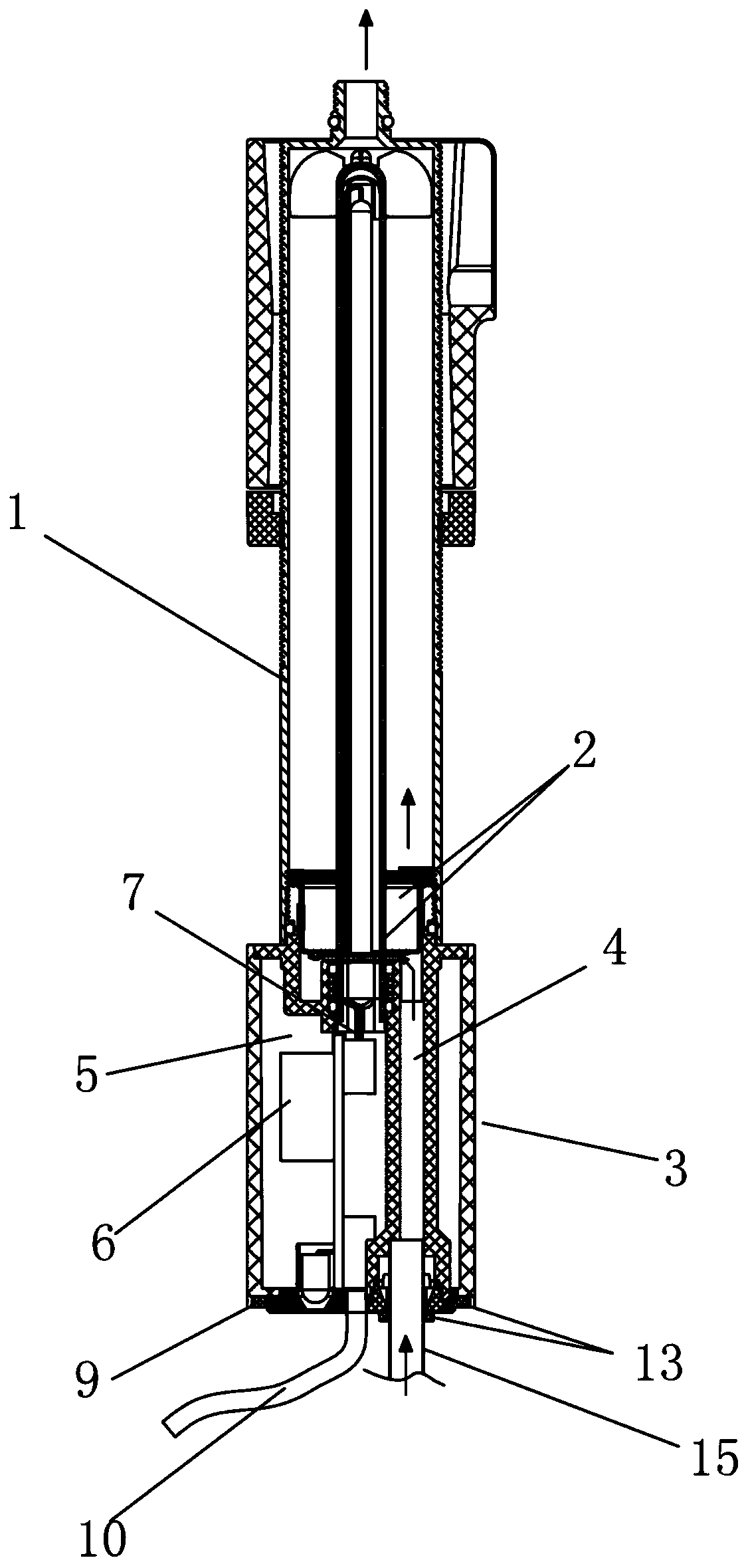
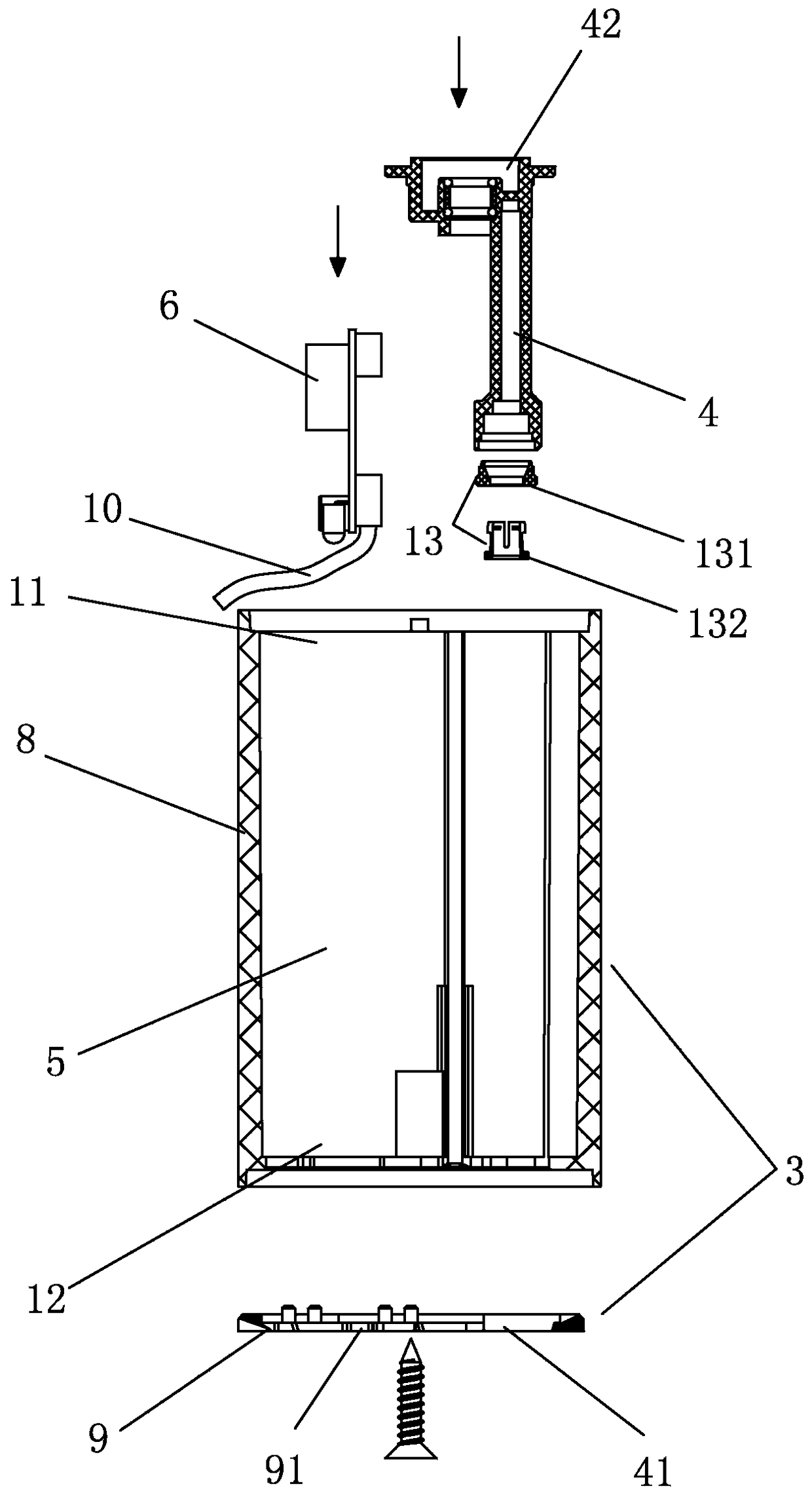
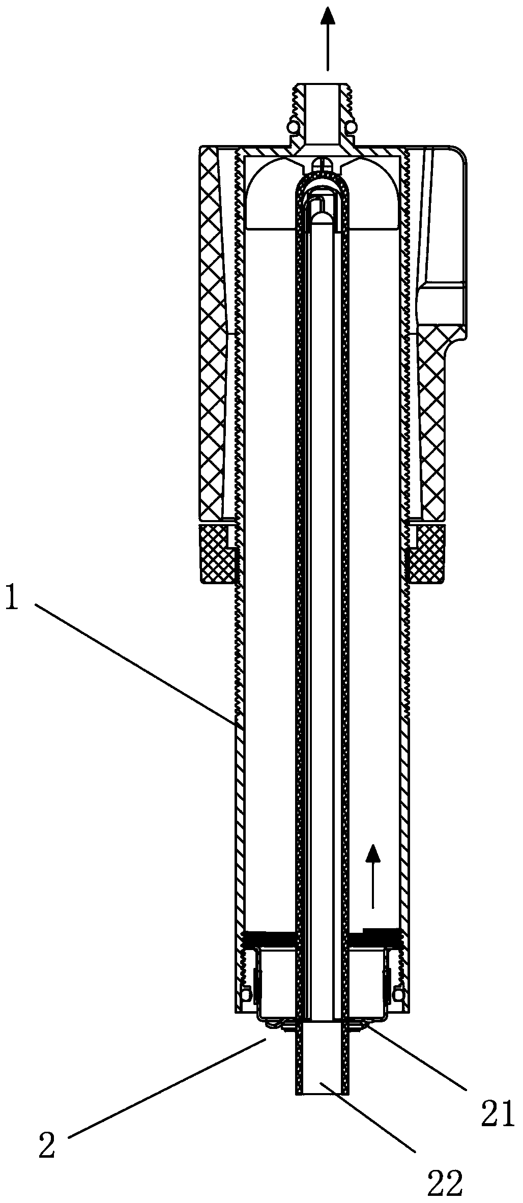
[0024] Such as Figure 1-Figure 3 As shown, the water and electricity integrated UV lamp assembly structure includes a UV lamp 1, one end of the UV lamp 1 is provided with a water and electricity connection end seat 2, and the water and electricity connection end seat 2 is provided with a water inlet interface 21 and a circuit interface 22, It is characterized in that it also includes a water and electricity connection housing 3, the water and electricity connection housing 3 is connected to the water and electricity connection end seat 2, the water and electricity connection housing 3 is provided with a water inlet area 4 and an electrical accessories installation area 5, the water inlet area 4. A water inlet 41 and a water outlet 42 are provided. The water inlet 41 is used as an external water source connection inlet and is arranged on the water and electri...


PUM


Abstract

The invention discloses a water and electricity integrated assembly structure of a UV (Ultraviolet) lamp. The water and electricity integrated assembly structure of the UV lamp comprises the UV lamp, wherein a water and electricity connecting end seat is arranged at one end of the UV lamp, and a water inlet port and a circuit interface are arranged on the water and electricity connecting end seat, the water and electricity integrated assembly structure of the UV lamp is characterized by further comprising a water and electricity connecting shell which is connected with the water and electricity connecting end seat, a water inlet area and an electrical accessory installation area are arranged on the water and electricity connecting shell, the water inlet area is provided with a water inlet and a water outlet, the water inlet is used as a joint access of external water sources, and arranged on the water and electricity connecting shell, the water outlet communicates with the water inlet port on the water and electricity connecting end seat, a printed circuit board(PCB) is arranged in the electrical accessory installation area, and penetrates through the circuit interface through a wire to be electrically connected with the UV lamp; according to the assembly structure of the UV lamp disclosed by the invention, a water route and a circuit are connected and arranged in the same shell by additionally arranging the water and electricity connecting shell to protect the connection of the water route and the circuit, in particular, enable water sealing of the circuit connection to be better, and further enable the appearance of the whole UV lamp assembly more beautiful, and achieve simple and reasonable structure.

Description

technical field [0001] The invention relates to a UV lamp, in particular to a hydroelectric integrated UV lamp assembly structure. Background technique [0002] As the application of ultraviolet (UV) sterilization technology in water treatment becomes more and more mature, the structural design requirements for UV sterilizers are also getting higher and higher; at present, traditional UV lamps generally include water inlet area and UV sterilization area. It flows into the UV sterilization area through the water inlet area, and the UV lamp tube sterilizes and disinfects the water flowing through the UV sterilization area. However, the existing UV lamp structure still has the following shortcomings: (1) The ports of the UV lamp need to be connected at the same time Waterway and circuit, however, because there is no protective jacket for the waterway and circuit connection, it not only affects its appearance, but also easily causes damage to the waterway and circuit connection;...

Claims


Application Information

Patent Timeline
Patent Type & Authority Patents(China)
IPC IPC(8): C02F1/32
CPCC02F1/325C02F2201/004C02F2303/04C02F2303/14
Inventor 陈小平
Owner FOSHAN VIOMI ELECTRICAL TECH
Why Eureka
Try Eureka