Combined insulating operating rod

An insulating operating rod and combined technology, which is applied to contact operating parts, lighting devices, emergency protection devices, etc., can solve the problem that the outer wall of the insulating rod body is easily wet or condensed water mist, and the long rod body of the insulating operating rod is inconvenient to carry. , operator's personal safety injury and other issues, to achieve the effect of easy night operation, avoid arm fatigue, simple and fast assembly

Inactive Publication Date: 2019-12-17
STATE GRID CORP OF CHINA +1
View PDF13 Cites 2 Cited by
  • Summary
  • Abstract
  • Description
  • Claims
  • Application Information

AI Technical Summary

Problems solved by technology

[0004] Insulated operating rods are divided into many models, the difference lies in the length, and there are still some defects in the traditional insulating operating rods: 1. Since there is no lighting device, it must be operated with a flashlight when repairing at night; 2. The long body of the insulating operating rod is not easy to carry. Convenient, cannot be combined quickly according to the required length;
[0006] 4. Before operating the insulating operating rod, an electroscope should be used to inspect the high-voltage lines and equipment. Two tools, the operating rod and the electroscope, are required at the same time, and these two tools are generally separated and independent, which makes maintenance The work procedures are cumbersome and inefficient;
[0007] 5. The rod body of the insulating operating rod is mostly smooth rod body. In rainy and humid weather, the outer wall of the insulating rod body is easy to be wet or condensed, so that the outer wall of the insulating rod body is charged. Injury to the personal safety of the operator

Method used


Image

  • Combined insulating operating rod
  • Combined insulating operating rod
  • Combined insulating operating rod

Examples


Embodiment 1

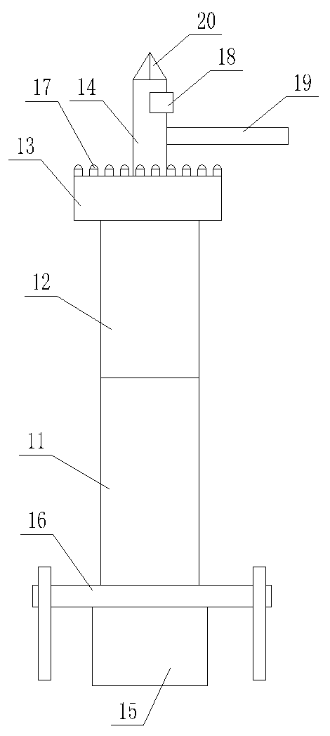
[0052] as attached figure 1 , 4 , 5 and 7;

[0053] A combined insulating operating rod, comprising a lower insulating operating rod 11, an upper insulating operating rod 12 connected to the lower insulating operating rod 11, and a back frame 16 arranged on one side of the lower insulating operating rod 11;

[0054] The back frame 16 is fixed on the lower insulating operating rod 11 through the arc back plate 15;

[0055] The upper end of the upper insulating operating rod 12 is provided with an operating base 13, an electric detection rod 14 vertically fixed on the operating base 13, a brake rod 19 fixed on the side of the electric detecting rod 14, and an operating base 13. The lighting strip 17 on the top and the side lamp 18 arranged on the side of the electric pole 14;

[0056] The light irradiation direction of the side light 18 is the same as that of the brake lever 19;

[0057] The top end of the test rod 14 is a metal pointed tip 20 used for testing equipment elec...

Embodiment 2

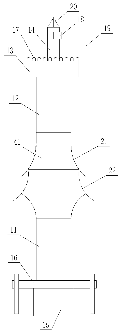
[0066] as attached figure 2 , 4 , 5, 6 and 7;

[0067] A combined insulating operating rod, comprising a lower insulating operating rod 11, an upper insulating operating rod 12 connected to the lower insulating operating rod 11, and a back frame 16 arranged on one side of the lower insulating operating rod 11;

[0068] The back frame 16 is fixed on the lower insulating operating rod 11 through the arc back plate 15;

[0069] The upper end of the upper insulating operating rod 12 is provided with an operating base 13, an electric detection rod 14 vertically fixed on the operating base 13, a brake rod 19 fixed on the side of the electric detecting rod 14, and an operating base 13. The lighting strip 17 on the top and the side lamp 18 arranged on the side of the electric pole 14;

[0070] The light irradiation direction of the side light 18 is the same as that of the brake lever 19;

[0071] The top end of the test rod 14 is a metal pointed tip 20 used for testing equipment ...

Embodiment 3

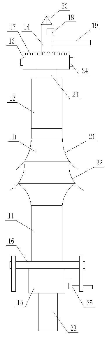
[0084] as attached image 3 , 4 , 8 and 9;

[0085] A combined insulating operating rod, comprising a lower insulating operating rod 11, an upper insulating operating rod 12 connected to the lower insulating operating rod 11, and a back frame 16 arranged on one side of the lower insulating operating rod 11;

[0086] The back frame 16 is fixed on the lower insulating operating rod 11 through the arc back plate 15;

[0087] The upper end of the upper insulating operating rod 12 is provided with an operating base 13, an electric detection rod 14 vertically fixed on the operating base 13, a brake rod 19 fixed on the side of the electric detecting rod 14, and an operating base 13. The lighting strip 17 on the top and the side lamp 18 arranged on the side of the electric pole 14;

[0088] The light irradiation direction of the side light 18 is the same as that of the brake lever 19;

[0089] The top end of the test rod 14 is a metal pointed tip 20 used for testing equipment elec...


PUM


Abstract

The invention discloses a combined insulating operating rod, which comprises a lower insulating operating rod, an upper insulating operating rod connected to the lower insulating operating rod, and aback frame arranged on one side of the lower insulating operating rod, wherein the back frame is fixed on the lower insulating operating rod through an arc-shaped back plate. The combined insulating operating rod has the advantages of being simple in structure and convenient and reliable to operate. The upper insulating operating rod, the lower insulating operating rod and a middle rainproof insulating rod are assembled through threaded connectors, on-site assembly is simple and rapid, labor is saved in operation, and the operation safety is high. The device is convenient to carry due to the strap structure, and arm fatigue caused by long-time hand lifting is avoided. When not in use, the rod can be detached into short rods and is convenient to carry, and the working efficiency is improved. The middle rainproof insulating rod is added, so that the rod is suitable for waterproof operation in cloudy and rainy days. A simple worm and gear mechanism is adopted to adjust the operation height, two hands for rod lifting can be thoroughly liberated, and more time and labor are saved.

Description

technical field [0001] The invention relates to the technical field of power distribution line maintenance, in particular to a combined insulating operating rod. Background technique [0002] The insulating operating rod is an insulating tool used to operate live equipment in a short time, such as turning on or off the high-voltage isolating switch, dropping the fuse, etc. Insulated operating rod, also known as gram rod, insulating rod, insulating rod, is an auxiliary tool commonly used by power system installation and maintenance personnel. The traditional rod (insulated operating rod) is mainly composed of two parts: the working head and the insulating rod. The insulating operating rod is a kind of electrical safety tool, its main function is to connect or disconnect the knife switch and drop insurance, etc., and it can also be used to disconnect or close most mechanical electrical equipment or lines. The range is very wide, and it is used in closing or opening the high-...

Claims


Application Information

Patent Timeline
Patent Type & Authority Applications(China)
IPC IPC(8): H01H3/02F21V33/00
CPCF21V33/008H01H3/02H01H2300/056
Inventor 苏凯耀张晓坤董浩张昊泽李汶采童泓博
Owner STATE GRID CORP OF CHINA
Why Eureka
Try Eureka