Internal combustion engine variable valve timing mechanism with simple structure

A valve timing and simple structure technology, applied in the direction of machines/engines, mechanical equipment, engine components, etc., can solve the problems of complex structure of the variable valve timing mechanism, and achieve the effect of simple structure and convenient maintenance

Inactive Publication Date: 2016-09-07
唐心昱
View PDF4 Cites 0 Cited by
  • Summary
  • Abstract
  • Description
  • Claims
  • Application Information

AI Technical Summary

Problems solved by technology

[0003] The purpose of the present invention is to solve the problem that the structure of the existing internal combustion engine variable valve timing mechanism is relatively complex and needs the support of the hydraulic system, and to provide a variable valve timing mechanism with a simple structure, which is different from the variable valve timing mechanism without variable valve timing. Compared with the time mechanism, it only needs to add a stepper motor, a sliding sleeve I (or III), a one-way thrust ball bearing, a sliding sleeve II (or IV), a return spring and an end cover I (or II) (excluding standard parts), the same kinetic energy of the existing variable valve timing mechanism can be achieved

Method used


Image

  • Internal combustion engine variable valve timing mechanism with simple structure
  • Internal combustion engine variable valve timing mechanism with simple structure
  • Internal combustion engine variable valve timing mechanism with simple structure

Examples


specific Embodiment approach 1

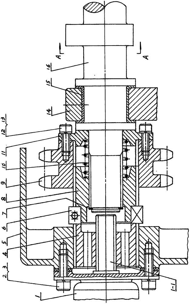
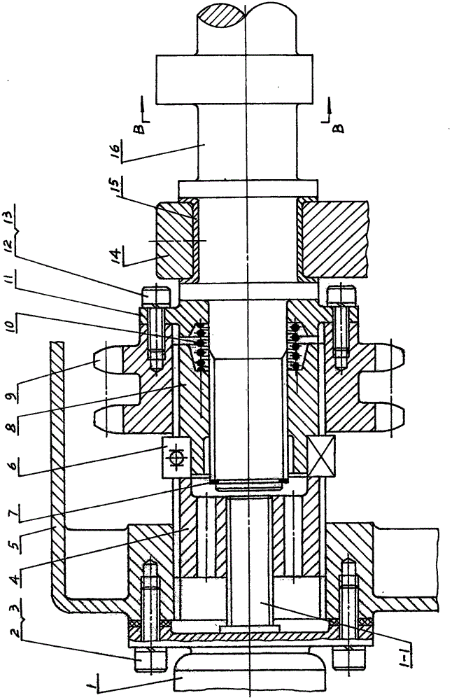
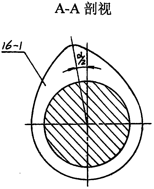
[0010] Specific implementation mode one: combine Figure 1 to Figure 15 Illustrate the specific embodiment, the present embodiment comprises a stepper motor (1), a sliding sleeve 1 (4), a dust cover (5), a one-way thrust ball bearing (6), a shaft circlip ( 7), a sliding sleeve II (8), a sprocket (9), a return spring (10), an end cover I (11) and a camshaft (16); put the stepper motor (1) The threaded shaft (1-1) is combined with the internal thread (4-2) of the sliding sleeve I (4) and packed into the straight-tooth internal spline (5-1) of the dust cover (5), and then the bolt (2 ) and spring washer (3) to fix the stepper motor (1) on the dust cover (5), and the sprocket (9) and end cover I (11) are fixed together with bolts (12) and spring washer (13) Finally, install the root of the straight-toothed external spline (16-2) of the camshaft (16), and then install the return spring (10) and sliding sleeve II (8) in sequence, and limit the position with the elastic circlip (7) ...

specific Embodiment approach 2

[0011] Specific embodiment two (applicable to the internal combustion engine of cylinder annular arrangement): combine Figure 16 ~ Figure 33Illustrate the specific embodiment, this embodiment comprises a stepper motor (1), a sliding sleeve III (18), a cylinder head cover (17), a one-way thrust ball bearing (6), a shaft circlip ( 7), a sliding sleeve IV (19), an intake convex plate (20), an exhaust convex plate (21), an end cover II (22) and a bevel gear central shaft (27); The threaded shaft (1-1) of the motor (1) is combined with the internal thread (18-1) of the sliding sleeve III (18) and put into the straight-tooth internal spline (17-2) of the cylinder head cover (17), Fix the stepper motor (1) on the cylinder head cover (17) with bolts (2) and spring washers (3), and put the exhaust convex plate (21) into the straight tooth outer flower of the bevel gear central shaft (27) key (27-1), then fix the air intake convex plate (20) and end cover II (22) together with bolts (...


PUM


Abstract

The invention relates to an internal combustion engine variable valve timing mechanism with a simple structure. A scheme 1, a stepping motor drives a slide sleeve I to move rightward through a threaded shaft of the stepping motor, the slide sleeve I pushes a slide sleeve II to move rightward through a single-direction thrust ball bearing, and a return spring is compressed, in this process, a helical tooth external spline of the slide sleeve II and a helical internal spline of a chain wheel interact each other to allow a camshaft to rotate clockwise relative to the chain wheel (left view); and in this time, the stepping motor rotates in reverse, and then drives the slide sleeve I to move leftward through the thread shaft of the stepping motor, the slide sleeve II moves leftward under the action of the return spring, and in this process, the helical tooth external spline of the slide sleeve II and the helical internal spline of a chain wheel interact each other to allow the camshaft to rotate counterclockwise relative to the chain wheel (left view). differences between a scheme 2 and the scheme 1 are that an shaft end of a bevel gear central shaft is a straight tooth external spline, a slide sleeve IV is a straight tooth internal spline and a helical tooth external spline, an air inlet raised disk is a helical tooth internal spline, and an air discharging raised disk is a straight internal spline.

Description

technical field [0001] The invention relates to a variable valve timing mechanism of an internal combustion engine. Background technique [0002] At present, the structure of the known variable valve timing mechanism for internal combustion engines is all more complicated, and needs the support of the hydraulic system. Figure 5-6 0) as an example, it can be seen that its structure is relatively complex and requires hydraulic system support. Contents of the invention [0003] The purpose of the present invention is to solve the problem that the structure of the existing internal combustion engine variable valve timing mechanism is relatively complex and needs the support of the hydraulic system, and to provide a variable valve timing mechanism with a simple structure, which is different from the variable valve timing mechanism without variable valve timing. Compared with the time mechanism, it only needs to add a stepper motor, a sliding sleeve I (or III), a one-way thrust...

Claims


Application Information

Patent Timeline
Patent Type & Authority Applications(China)
IPC IPC(8): F01L1/34
CPCF01L1/34
Inventor 唐心昱
Owner 唐心昱
Why Eureka
Try Eureka