Axial-flow magnetic levitation permanent magnet hydro-generator

A hydro-generator and magnetic levitation technology, which is applied in the directions of hydropower generation, engine components, machines/engines, etc., can solve the problems of power consumption, complex structure and low efficiency.

Inactive Publication Date: 2018-11-16
CHONGQING UNIV OF TECH
View PDF2 Cites 0 Cited by
  • Summary
  • Abstract
  • Description
  • Claims
  • Application Information

AI Technical Summary

Problems solved by technology

Not very efficient due to the friction of the pulley; and inconvenient landing of the rotor
[0005] The magnetic levitation hydroelectric generator disclosed in patent 201310358998.8 adopts an axial flow turbine with relatively large thrust in the axial direction. It is necessary to use a hybrid magnetic levitation including electromagnetic to ensure the complete suspension of the runner. Therefore, the structure is complex and costly, and there is additional power consumption.

Method used


Image

  • Axial-flow magnetic levitation permanent magnet hydro-generator

Examples


Embodiment Construction

[0021] The technical solutions in the embodiments of the present invention will be clearly and completely described below in conjunction with the accompanying drawings in the embodiments of the present invention. Obviously, the described embodiments are only a part of the embodiments of the present invention, rather than all the embodiments. Based on the embodiments of the present invention, all other embodiments obtained by those of ordinary skill in the art without creative work shall fall within the protection scope of the present invention.

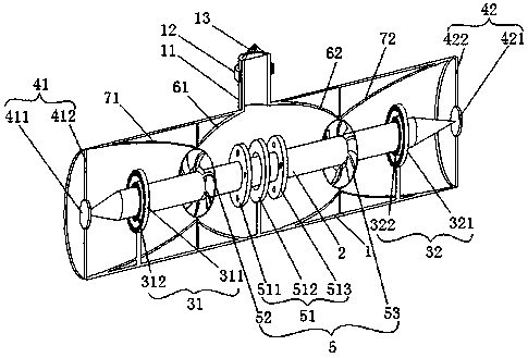
[0022] See figure 1 , figure 1 It is a schematic structural diagram of an embodiment of the axial flow magnetic levitation permanent magnet hydroelectric generator of the present invention. The axial flow magnetic levitation permanent magnet hydroelectric generator of this embodiment includes a volute 1 with a water inlet, a rotor shaft 2 arranged in the volute 1 and coaxial with the volute 1 The left levitation magnetic bearing 31 an...


PUM


Abstract

The invention discloses an axial flow magnetic suspension permanent magnet hydro-generator. The axial flow magnetic suspension permanent magnet hydro-generator comprises a volute, a rotor shaft, a left suspension magnetic bearing, a right suspension magnetic bearing, a left limiting assembly, a right limiting assembly, a hydro-generator set, a first flow guiding assembly and a second flow guiding assembly, wherein the volute is provided with a water inlet; the rotor shaft is arranged in the volute and the rotor shaft and the volute are provided with the same axis; the left suspension magnetic bearing and the right suspension magnetic bearing are arranged in the volute and the left suspension magnetic bearing, the right suspension magnetic bearing and the volute are provided with the same axis; the left limiting assembly and the right limiting assembly are arranged at the two ends of the volute correspondingly and used for axially limiting the rotor shaft; the hydro-generator set is arranged on the rotor shaft; the first flow guiding assembly is arranged in the volute and used for guiding entered water to the hydro-generator set; and the second flow guiding assembly is used for guiding water in a cavity out of the two ends of the volute. The two ends of the rotor shaft are arranged in the left suspension magnetic bearing and the right suspension magnetic bearing in a penetrating mode correspondingly and always suspended on the axis of the volute and not eccentric under the radial repulsive force action of the left suspension magnetic bearing and the right suspension magnetic bearing. The two ends of the rotor shaft abut against the left limiting assembly and the right limiting assembly correspondingly. The axial flow magnetic suspension permanent magnet hydro-generator is simple in structure and high in power generating efficiency.

Description

Technical field [0001] The invention relates to the field of hydroelectric power generation, in particular to an axial flow magnetic suspension permanent magnet hydroelectric generator. Background technique [0002] Micro-hydropower is a hydropower system that uses small water resources with low head and small flow near the power load to generate electricity, without substation, and is directly used by users. Micro-hydropower is an important way to solve the contradiction between environment and resources. It has important strategic significance for promoting rural electrification, sustainable development and overall social progress in my country and other countries, especially developing countries. [0003] However, the current micro-hydro power generation efficiency is generally low. For example, in Europe and the United States, the efficiency of micro-hydropower can reach 70-80% by speed regulation. In order to reduce development costs, China uses non-speed regulation and dummy ...

Claims


Application Information

Patent Timeline
Patent Type & Authority Patents(China)
IPC IPC(8): F03B13/00F03B3/04F03B3/16F03B11/06F03B11/02F03B11/08
CPCF03B3/04F03B3/16F03B11/02F03B11/06F03B11/08F03B13/00Y02E10/20
Inventor 古亮陈龙陈新岗蒋新孙军尹泽龙
Owner CHONGQING UNIV OF TECH
Why Eureka
Try Eureka