a heat exchange system

A heat exchange system and heat exchange plate technology, applied in the field of heat exchange, can solve the problems of mutual infection between the condensation area and the evaporation area, damage to the evaporation scene of the evaporator, and failure to achieve optimal energy efficiency, so as to increase the temperature difference, improve efficiency, and prolong The effect of service life

Active Publication Date: 2019-04-12
唐玉敏 +1
View PDF9 Cites 0 Cited by
  • Summary
  • Abstract
  • Description
  • Claims
  • Application Information

AI Technical Summary

Problems solved by technology

However, the condensation waste heat carried by the working fluid in the second link reduces the temperature difference between the working fluid in the evaporator and the external environment, destroying the evaporation scene of the evaporator
Therefore, in the traditional air-conditioning heat pump refrigeration / heating system, the condensation area and the evaporation area are not completely independent and isolated. The mutual infection of the districts, the energy efficiency of the whole system cannot be optimal

Method used


Image

  • a heat exchange system
  • a heat exchange system
  • a heat exchange system

Examples


Embodiment 1

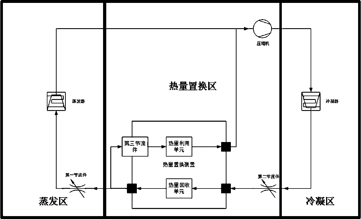
[0040] like Figure 4 It is a heating system, including a compressor, a condenser, an evaporator, a first throttling piece, a second throttling piece, and a heat replacement device connected through a working medium flow channel. The outlet of the compressor is connected to the inlet of the condenser, the outlet of the condenser is connected to the inlet of the second throttle, the outlet of the third throttle is connected to the inlet of the heat displacement device, and the first outlet of the heat displacement device is connected to the first throttle The inlet of the part, the outlet of the first throttling part is connected to the inlet of the evaporator, and the outlet of the evaporator is connected to the suction port of the compressor. When the working medium flows in the working medium flow channel, it absorbs the heat from the external environment of the evaporator and releases it into the environment where the condenser is located, providing heat for the environment...

Embodiment 2

[0049] like Figure 5 It is a heating system, including a compressor, a condenser, an evaporator, a first throttling piece, a second throttling piece, and a heat replacement device connected through a working medium flow channel. Among them, the evaporator includes an ordinary evaporator and a heat collecting plate (a heteropolymer heat absorbing plate that absorbs heat passively). The outlet of the compressor is connected to the inlet of the condenser, the outlet of the condenser is connected to the inlet of the second throttle, the outlet of the third throttle is connected to the inlet of the heat displacement device, and the first outlet of the heat displacement device is connected to the first throttle The inlet of the part, the outlet of the first throttling part is connected to the inlet of the evaporator, and the outlet of the evaporator is connected to the suction port of the compressor. When the working medium flows in the working medium flow channel, it absorbs the ...

Embodiment 3

[0053] like Figure 6 It is a heating system, including a compressor, a condenser, an evaporator, a first throttling piece, a second throttling piece, and a heat replacement device connected through a working medium flow channel. Among them, the evaporator includes an ordinary evaporator and a heat collecting plate (a heteropolymer heat absorbing plate that absorbs heat passively). The outlet of the compressor is connected to the inlet of the condenser, the outlet of the condenser is connected to the inlet of the second throttle, the outlet of the third throttle is connected to the inlet of the heat displacement device, and the first outlet of the heat displacement device is connected to the first throttle The inlet of the part, the outlet of the first throttling part is connected to the inlet of the evaporator, and the outlet of the evaporator is connected to the suction port of the compressor. When the working medium flows in the working medium flow channel, it absorbs the ...


PUM


Abstract

A heat exchange system, comprising an evaporator, a compressor, a condenser, and a first throttling member connected through a working fluid channel; the outlet of the evaporator is connected to the inlet of the compressor, and the outlet of the compressor connected to the inlet of the condenser, the outlet of the condenser is connected to the inlet of the first throttling member, and the outlet of the first throttling member is connected to the inlet of the evaporator; it is characterized in that: the condenser A heat replacement zone is provided between the outlet and the inlet of the first restrictor. The heat replacement area established between the condenser and the first throttling member isolates the condensation area and the evaporation area of ​​the system, while improving condensation, it also isolates the influence of condensation waste heat on the evaporation area, so that the energy efficiency of the system is greatly improved .

Description

technical field [0001] The invention relates to the technical field of heat exchange, in particular to a heat exchange system. Background technique [0002] like figure 1 , traditional air conditioning and heat pump heating / refrigeration systems include compressors, condensers, throttling parts, and evaporators. Compressed gas with high temperature and high pressure flows through the condenser to release heat, and finally enters the evaporator after being depressurized by the throttle. The working medium continuously absorbs and releases heat during the circulation process in the system to realize system heating / cooling. [0003] When the heating / refrigerating system is used for heating, the condenser is installed in the environment that needs to be heated, and the working fluid absorbs the heat in the environment where the evaporator is located in the evaporator, and is transported to the condenser through the working medium flow channel The heat is released in the air t...

Claims


Application Information

Patent Timeline
Patent Type & Authority Patents(China)
IPC IPC(8): F25B13/00F25B41/06F25B41/30
CPCF25B13/00F25B41/31
Inventor 唐玉敏虞红伟
Owner 唐玉敏
Why Eureka
Try Eureka