
Rapid detection pVTt methodgas flow standard device and detection method

A gas flow, standard device technology, applied in measurement devices, test/calibration devices, liquid/fluid solid measurement, etc., can solve the problems of urgent need to expand the verification range, time-consuming temperature field stabilization, and small number of devices, etc. The effect of the verification cycle, the shortening of the verification time, and the simple, reasonable and effective mechanism

Inactive Publication Date: 2016-09-07
CHINA JILIANG UNIV
View PDF7 Cites 16 Cited by
  • Summary
  • Abstract
  • Description
  • Claims
  • Application Information

AI Technical Summary

Problems solved by technology

[0004] The current pVTt method gas flow standard device in my country can detect the flow range up to 2000m 3 / h, the minimum is 0.001m 3 / h, but there are not many such devices in China, and with the development of the flow measurement range towards the polarized direction, the verification range needs to be expanded urgently. In addition, many aerodynamic problems still need to be studied and solved
[0005] The pVTt method gas flow device still has the following problems: In order to ensure the measurement accuracy of the pVTt method device, the average temperature and pressure in the standard container must be taken out for the calculation of mass flow when the temperature field is sufficiently stable, but the volume is large It takes a long time to evacuate the standard container and stabilize the temperature field after the air intake is completed. It takes about an hour, and the entire verification cycle is relatively long.

Method used


Image

  • Rapid detection pVTt methodgas flow standard device and detection method
  • Rapid detection pVTt methodgas flow standard device and detection method
  • Rapid detection pVTt methodgas flow standard device and detection method

Examples


Embodiment Construction

[0040] The present invention will be described in further detail below in conjunction with the accompanying drawings and specific embodiments.

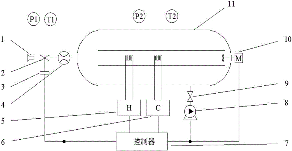
[0041] Such as figure 1 As shown, the present invention includes a standard container 11, a controller 7, a heating device 5, a refrigeration device 6, an electric fan 10 and a vacuum pump 8; The flow sensor 4 is connected to the front end of the transverse air duct, and the rear end of the standard container 11 is provided with an electric fan 10, and its electric fan is placed in the rear end of the standard container 11 transverse air duct. The standard container 11 is connected with a vacuum pump 8, a heating device 5 and a cooling device 6, the upper ends of the heating device 5 and the cooling device 6 extend into the horizontal air duct, the flow sensor 4, the heating device 5, the cooling device 6, the electric fan 10 and the vacuum pump 8 Both are connected to the controller 7.

[0042] The flow sensor 4 of the present inve...


PUM


Abstract

The invention discloses a rapid detection pVTt methodgas flow standard device and a detection method. The device comprises a standard container, a controller, a heating device, a refrigeration device, an electric fan, and a vacuum pump. The standard container is internally provided with a horizontal air channel from the front end to the rear end. A detected sonic nozzle is connected with the front end of the horizontal air channel through a flow sensor. The rear end of the horizontal air channel is provided with the electric fan. The standard container is connected with the vacuum pump, the heating device, and the refrigeration device. The upper ends of the heating device and the refrigeration device extend into the horizontal air channel. A flow sensor, the heating device, the refrigeration device, the electric fan, and the vacuum pump are connected with the controller. The method comprises: adjusting temperature to keep constant temperature, measuring parameters of the balance states of the standard container before air intake and after air intake, calculating to obtain detected mass flow rate, comparing the detected mass flow rate with theoretical mass flow rate, to obtain a detection result of whether qualified. The device is simple in structure, low in price, high in measuring precision, high in measuring efficiency, and repeatability is better than 0.06%.

Description

technical field [0001] The invention relates to a standard device, in particular to a rapid verification pVTt method gas flow standard device and verification method. Background technique [0002] The pVTt method gas flow detection device is a widely used primary gas flow standard metering device and equipment. Its accuracy level is high, and the measurement uncertainty U can reach 0.07% or higher. Venturi is usually used as a secondary standard. Primary standard devices and equipment for traceability of critical flow flowmeters such as nozzles and sonic nozzles. [0003] At present, the primary standard devices widely used mainly include bell jar type, active piston type, pVTt method and mt method gas flow standard devices, etc. In the primary standard device, the volume of the standard container of the pVTt method gas flow standard device is fixed, and the parameters such as pressure and temperature involved in the flow calculation are obtained through static measurement,...

Claims


Application Information

Patent Timeline
Patent Type & Authority Applications(China)
IPC IPC(8): G01F25/00
CPCG01F25/17
Inventor 徐志鹏李澜吉洪育仙
Owner CHINA JILIANG UNIV
Learn More