
Plasma reactor and method for decomposing a hydrocarbon fluid

A technology of plasma and hydrocarbon fluids, applied in the direction of plasma, chemical methods for reacting gases with non-granular solids, chemical instruments and methods, etc.

Inactive Publication Date: 2016-09-07
CCP TECH GMBH
View PDF5 Cites 1 Cited by
  • Summary
  • Abstract
  • Description
  • Claims
  • Application Information

AI Technical Summary

Problems solved by technology

Hot hydrogen accumulates especially in the free space 17' and this leads to a large heat loss
Furthermore, there is a large heat build-up in this region, resulting in temperatures as high as 2500°C

Method used


Image

  • Plasma reactor and method for decomposing a hydrocarbon fluid
  • Plasma reactor and method for decomposing a hydrocarbon fluid
  • Plasma reactor and method for decomposing a hydrocarbon fluid

Examples


Embodiment Construction

[0022] In the following description, the terms "top", "bottom", "right side" and "left side" and similar terms relate to the orientation and configuration shown in the drawings and are only intended to describe the embodiments. These terms may indicate preferred configurations and are not intended to be limiting. In the context of this specification, the term "hydrocarbon fluid" means a fluid (gas, aerosol, liquid) containing hydrocarbons.

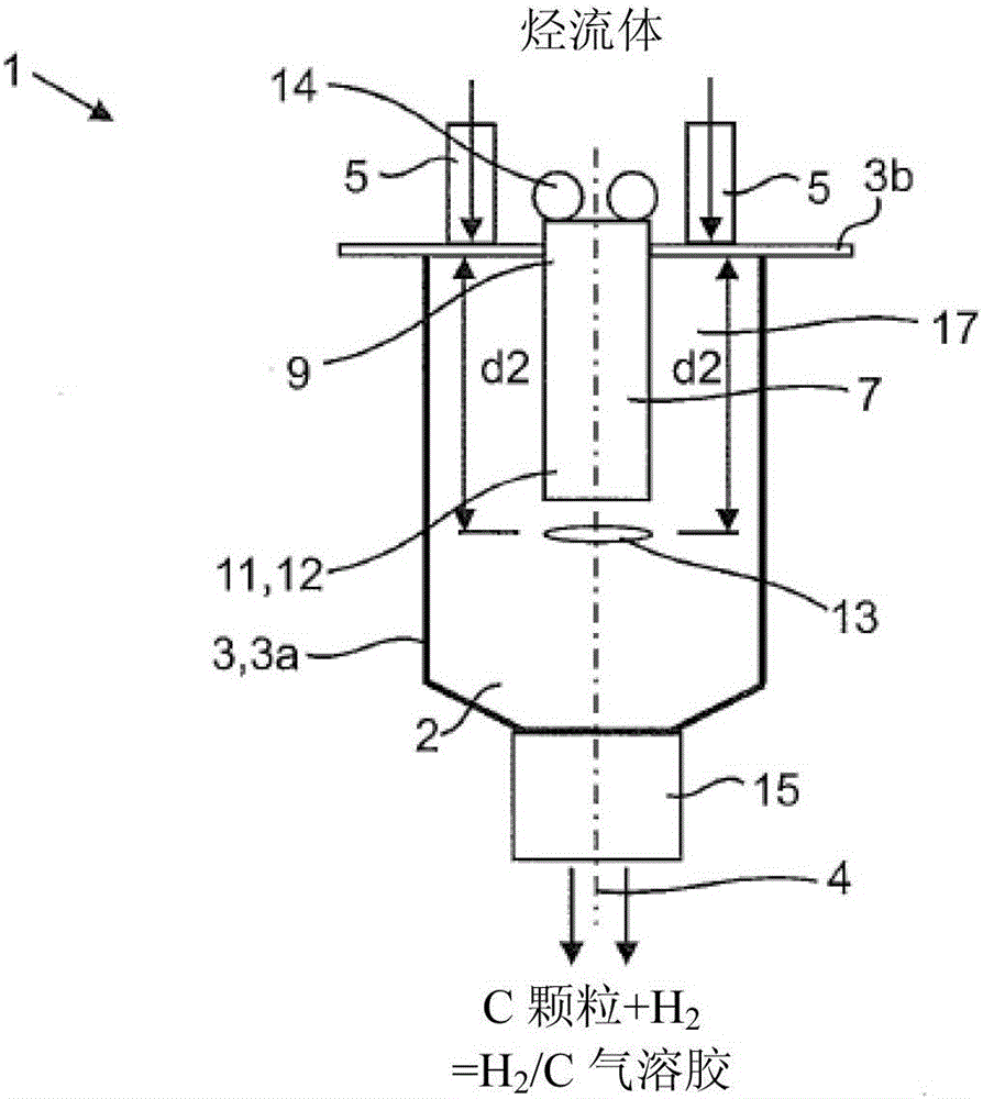
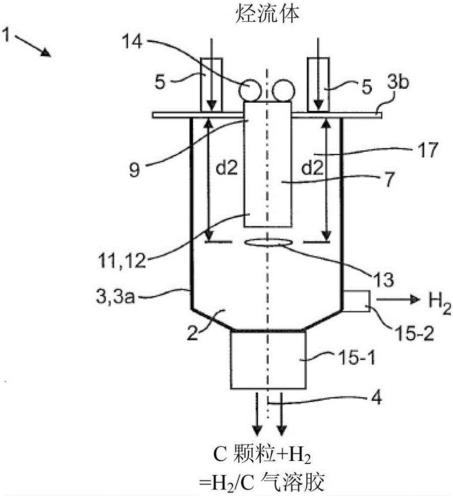
[0023] A plasma reactor 1 according to the present disclosure comprises a reactor chamber 2 closed by a reactor wall 3 having a lower portion 3a and a cover 3b. The reactor chamber 2 can also be divided at positions other than those shown in the figures. The reactor chamber 2 is substantially cylindrical and has a central axis 4 . A plasma burner 7 with elongated electrodes (not shown in detail) is fixed to the cover 3b of the reactor wall 3 . The plasma burner 7 has a base part 9 fixed to the reactor wall 3 (here, in particular, the co...


PUM


Abstract

In a plasma reactor (1) for decomposing a hydrocarbon fluid, the deposition of C particles is to be reduced or completely prevented. In order to achieve this object, there is described a plasma reactor (1) for decomposing a hydrocarbon fluid which comprises a reactor chamber (2) enclosed by a reactor wall (3, 3a) and having at least one hydrocarbon fluid inlet (5) and at least one outlet (15), and in addition it comprises a plasma burner (7) having at least two elongated electrodes which each have a base part (9) that is fixed to the reactor wall (3b) and a burner part (11) which projects into the reactor chamber (2) and has a free end. The hydrocarbon fluid inlet (5) opens out into the reactor chamber (2) in such a manner that a hydrocarbon fluid flowing out therefrom flows in a space between the reactor wall and the electrodes along at least one electrode to the free end (12) thereof. A high flow rate of the fluid is thereby achieved and the direction of flow of the incoming fluid is directed away from the hydrocarbon fluid inlet (5).

Description

technical field [0001] The present invention relates to plasma reactors for the decomposition of hydrocarbon fluids and methods of operating plasma reactors. Background technique [0002] Figure 5 Depicted is a known plasma reactor 1', which was used in the 1990s as a test reactor for the production of carbon granules (or called C granules). A known plasma reactor 1' comprises a reactor chamber 2' closed by a reactor wall 3' having a lower part 3a' and a cover 3b'. The reactor chamber 2' is substantially cylindrical and has a central axis 4'. A plurality of hydrocarbon fluid inlets 5' are provided on the outer cylindrical wall for directing hydrocarbon fluid in radial direction. A plasma burner 7' comprising elongated electrodes (which are not shown in detail) is fixed to the cover 3b' of the reactor wall 3'. The plasma burner 7' has a base portion 9' fixed to the cover 3b' of the reactor wall 3'. At the other end of the plasma burner 7' opposite the base part 9', the p...

Claims


Application Information

Patent Timeline
Patent Type & Authority Applications(China)
IPC IPC(8): B01J19/08C01B3/24
CPCC01B3/24B01J2219/00247B01J2219/0809B01J2219/0826B01J2219/0869B01J2219/0877B01J2219/0884B01J2219/0894H05H1/48C01B2203/0272C01B2203/062C01B2203/0861C01B2203/1241Y02E60/36C01B32/05B01J19/088B01J2219/00351B01J2219/0059B01J2219/00594B01J2219/00596B01J2219/0072C10G2/35C10G2300/1025B01J7/02B01J15/005B01J2219/0875C01B3/06
Inventor 欧拉芙·库尔
Owner CCP TECH GMBH
Learn More