Automatic setting machine

A stacking machine, automatic technology, applied in the stacking of objects, unstacking of objects, transportation and packaging, etc., can solve the problems of brick falling, brick falling damage, large impact force, etc., to prevent extrusion from being affected damage effect

Active Publication Date: 2016-09-14
徐州博创建设发展集团有限公司
View PDF6 Cites 0 Cited by
  • Summary
  • Abstract
  • Description
  • Claims
  • Application Information

AI Technical Summary

Problems solved by technology

The gripper of the green brick machine in this patent document is connected to the motor reducer through the lifting belt, so that the grasped bricks can be lifted upwards, but because the gripping force of the green brick machine gripper cannot be adjusted, especially when clamping bricks of different sizes When the adobe is processed, it is easy to cause the adobe to fall and be damaged by extrusion, which reduces the quality and efficiency of the coded adobe. adobe quality

Method used


Image

  • Automatic setting machine
  • Automatic setting machine
  • Automatic setting machine

Examples


Embodiment 1

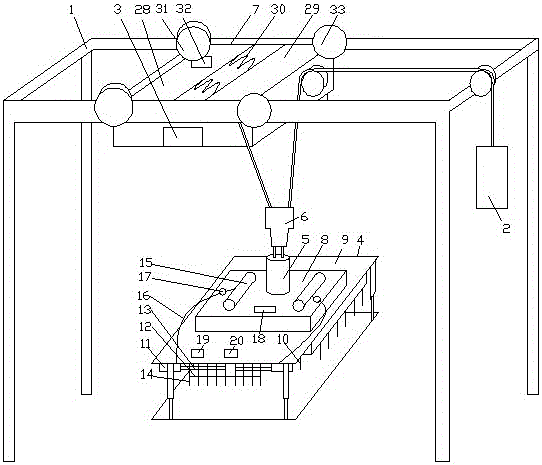
[0031] see figure 1, an automatic stacking machine, comprising a frame 1, a counterweight 2, a main frame 3, a clamping device 4 electrically connected to the main frame 3, a rotating device 5, a lifting device 6 and a walking device 7, and the running device 7 is slidably connected to the On the beam of the frame 1, the blank clamping device 4 includes a chuck 8, a telescopic frame 9 connected to the chuck 8 and multiple rows of clamps 10 connected to the inner wall of the telescopic frame 9, the chuck 8 and the rotating device 5 Fixedly connected, clamp 10 is made of cylinder 11, connecting rod 12, telescopic rod 13 and at least two splints 14 side by side, cylinder 11 is fixed on telescopic frame 9, telescopic rod 13 is connected with the piston rod of cylinder 11, splint 14 wears on On the telescopic rod 13, two adjacent splints 14 are connected by connecting rods 12 to form a linkage. The chuck 8 is connected with an air storage tank 15, and the cylinder 11 communicates w...

Embodiment 2

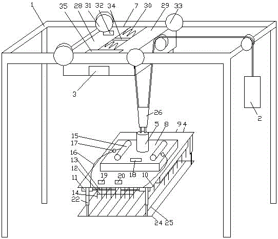
[0034] see figure 2 , an automatic stacking machine, comprising a frame 1, a counterweight 2, a main frame 3, a clamping device 4 electrically connected to the main frame 3, a rotating device 5, a lifting device 6 and a walking device 7, and the running device 7 is slidably connected to the On the beam of the frame 1, the blank clamping device 4 includes a chuck 8, a telescopic frame 9 connected to the chuck 8 and multiple rows of clamps 10 connected to the inner wall of the telescopic frame 9, the chuck 8 and the rotating device 5 Fixedly connected, clamp 10 is made of cylinder 11, connecting rod 12, telescopic rod 13 and at least two splints 14 side by side, cylinder 11 is fixed on telescopic frame 9, telescopic rod 13 is connected with the piston rod of cylinder 11, splint 14 wears on On the telescopic rod 13, two adjacent splints 14 are connected by connecting rods 12 to form a linkage. The chuck 8 is connected with an air storage tank 15, and the cylinder 11 communicates...

Embodiment 3

[0038] see figure 2 , an automatic stacking machine, comprising a frame 1, a counterweight 2, a main frame 3, a clamping device 4 electrically connected to the main frame 3, a rotating device 5, a lifting device 6 and a walking device 7, and the running device 7 is slidably connected to the On the beam of the frame 1, the blank clamping device 4 includes a chuck 8, a telescopic frame 9 connected to the chuck 8 and multiple rows of clamps 10 connected to the inner wall of the telescopic frame 9, the chuck 8 and the rotating device 5 Fixedly connected, clamp 10 is made of cylinder 11, connecting rod 12, telescopic rod 13 and at least two splints 14 side by side, cylinder 11 is fixed on telescopic frame 9, telescopic rod 13 is connected with the piston rod of cylinder 11, splint 14 wears on On the telescopic rod 13, two adjacent splints 14 are connected by connecting rods 12 to form a linkage. The chuck 8 is connected with an air storage tank 15, and the cylinder 11 communicates...


PUM


Abstract

The invention discloses an automatic setting machine. The automatic setting machine comprises a green brick clamping device. The automatic setting machine is characterized in that the green brick clamping device comprises a clamping disc, a telescopic frame and a clamp, and the clamp is composed of air cylinders, connecting rods, telescopic rods and at least two clamping plates arranged side by side; the telescopic rods and piston rods of the air cylinders are connected, the clamping plates penetrate the telescopic rods, every two adjacent clamping plates are connected to form linkage through the corresponding connecting rod, the clamping disc is provided with air storage tanks, and the air cylinders communicate with the air storage tanks through air distributing pipes; the air inlet ends of the air distributing pipes are connected with air pressure adjusters, the clamping disc is provided with a bijection type photoelectric sensor, and the telescopic frame is provided with an electric induction type sensor and a magnetic sensor; and a walking device comprises a first frame plate, a second frame plate and spring columns, the first frame plate is provided with a driving wheel driven by a servo motor, and the second frame plate is provided with a driven wheel. The walking device of the automatic setting machine can buffer inertia impact force in a self-adaption manner when pausing, the green brick moving stability is improved, and the green brick quality and the green brick stacking efficiency are guaranteed.

Description

technical field [0001] The invention relates to the technical field of sintered brick mechanical equipment, in particular to an automatic brick stacking machine capable of quickly stacking bricks. Background technique [0002] The automatic stacking machine is a mechanical device that automatically divides, grabs, moves and stacks bricks in sequence. The automatic stacking machine is mainly composed of a splitting device, a blank clamping device, a walking device, a lifting device, a rotating device, and a hydraulic system. It is composed of an electrical system, etc., wherein the lifting device is connected with the traveling device and the rotating device, and the rotating device is connected with the clamping device. Compared with the manual stacking method, it has the advantages of high production efficiency and good stacking quality of bricks. [0003] When the automatic blank stacking machine is working, when the blank cutting machine pushes the cut bricks to the sepa...

Claims


Application Information

Patent Timeline
IPC IPC(8): B65G61/00
CPCB65G61/00
Inventor 何娟石一利
Owner 徐州博创建设发展集团有限公司
Why Eureka
Try Eureka