Automatic oil edge production line

A production line and oil edge technology, applied in the field of leather oil edge, can solve problems such as low efficiency, and achieve the effect of improving work efficiency, accurate feeding operation, and ensuring accuracy

Active Publication Date: 2016-09-14
张志军
View PDF4 Cites 9 Cited by
  • Summary
  • Abstract
  • Description
  • Claims
  • Application Information

AI Technical Summary

Problems solved by technology

The automatic oil edge machine is a device that uses the adhesive force of the edge oil itself to adhere the oil to the edge of the leather. At present, most of the existing automatic oil edge equipment are semi-automatic, which can only

Method used


Image

  • Automatic oil edge production line
  • Automatic oil edge production line
  • Automatic oil edge production line

Examples


Embodiment 1

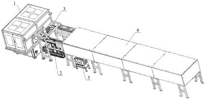
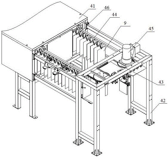
[0043] An automatic oil edge production line, its overall structure is as follows figure 1 As shown, it includes the control mechanism 5 and the oil edge machine 1, the material hanging mechanism 2 and the drying mechanism 4 arranged successively. The connection between the drying mechanism 4 and the material hanging mechanism 2 is also provided with a clamping mechanism 3 and a discharging mechanism. , the control mechanism is respectively connected with the oil edge machine 1, the material hanging mechanism 2, the clamping mechanism 3, the drying mechanism 4 and the controlled end of the unloading mechanism, and is used to control each mechanism to coordinate and complete the oil edge operation.

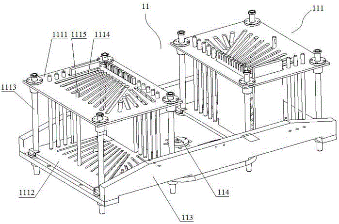
[0044] The oil edge machine 1 is used for oil edge operation on the blank, including a feeding mechanism 11 , a rotating manipulator 12 , a shaping mechanism 13 and an oil edge mechanism 14 . In the present invention, the rotary manipulator is a four-station structure arranged in a...

Embodiment 2

[0075] The difference between this embodiment and Embodiment 1 is that the structure of the oil transfer mechanism in the oil edge head is different. In this embodiment, the structure of the oil edge head 144 is as follows Figure 9 with Figure 10 shown.

[0076] The oil delivery mechanism includes an oil side motor 1447, a driving wheel 1443, a lower guide wheel 1448, a tensioner wheel 1444, an upper guide wheel 1445, a belt guide mechanism 1449 and an oil delivery belt 1446. Both the driving wheel 1443 and the lower guide wheel 1448 are arranged on one side wall of the oil storage box 1442, and are immersed in the oil of the oil storage box 1442; Guide wheel 1445 is fixedly arranged on the support top, and is positioned at the top of driving wheel 1443; The wheel 1444 and the lower guide wheel 1448 are located in the same vertical plane, and are surrounded by the oil transfer belt 1446 to form a quadrilateral structure; the belt guide mechanism 1449 is arranged at the con...


PUM


Abstract

The invention discloses an automatic oil edge production line which comprises a control mechanism, an oil edge machine, a material hanging mechanism and a drying mechanism. The oil edge machine, a material hanging mechanism and a drying mechanism are sequentially connected. A clamping mechanism and a discharging mechanism are arranged on the connecting portion between the drying mechanism and the material hanging mechanism. The oil edge machine comprises a feeding mechanism, a shaping mechanism, an oil edge mechanism and a rotary mechanical arm. The rotary mechanical arm is of a four-station structure arranged in a cross mode. The feeding mechanism, the shaping mechanism, the oil edge mechanism and a material receiving end of the material hanging mechanism are arranged under the four stations of the rotary mechanical arm in the rotating direction of the rotary mechanical arm respectively. The control mechanism is connected with the controlled end of the rotary mechanical arm, the controlled end of the feeding mechanism, the controlled end of the shaping mechanism, the controlled end of the oil edge mechanism, the controlled end of the material hanging mechanism, the controlled end of the clamping mechanism, the controlled end of the drying mechanism and the controlled end of the discharging mechanism. Under control of the control mechanism, all the mechanisms are coordinated to cooperate to work, the whole oil edge operation is finished automatically under the circumstance without manual interference, and the working efficiency is improved greatly.

Description

Technical field [0001] The present invention involves the field of leather oil edges, especially an automatic oil edge production line. Background technique [0002] During the leather processing process, because the edges of the leather materials are relatively rough, if it is made of products without processing, it will definitely affect the product aesthetics. Therefore, before the leather material is made into the finished product, the cutting edges of the leather after cutting are required.Traditional leather oil edges generally use manual operation, and there are problems with low work efficiency and uneven oil. [0003] With the development of science and technology, the emergence of automatic oil edge machines has greatly improved the efficiency of leather oil edges.The automatic oil edge is a device that adheres to the edge of the edge oil itself to adhere to the edge of the leather edge. Most of the current automatic oil edge equipment is semi -automatic, which can only...

Claims


Application Information

Patent Timeline
IPC IPC(8): C14B1/58C14B17/06C14B17/00C14B15/04
CPCC14B1/58C14B15/04C14B17/00C14B17/06C14B2700/07
Inventor 张志军
Owner 张志军
Why Eureka
Try Eureka