Knitted fabric sized edge pre-drying device of tentering setting machine

A tenter setting and pre-drying technology, which is used in textiles and papermaking, textile processing machine accessories, textile material processing, etc. , to achieve the effect of reducing energy consumption, reducing enterprise costs, and preventing heat loss

Active Publication Date: 2016-09-14
JIANGSU LITTLE SUN TECH DEV CO LTD
View PDF6 Cites 3 Cited by
  • Summary
  • Abstract
  • Description
  • Claims
  • Application Information

AI Technical Summary

Problems solved by technology

However, after the selvedge is sizing, there will be inconsistent dryness and humidity between the fabric surface and the selvage edge, which will make it difficult to control the setting time when the fabric is heated and set in the drying room as a whole. Suction edge effect; long setting time may affect the quality of the cloth surface, and the phenomenon of yellowing of the cloth surface may occur
Therefore, some printing and dyeing factories use the method of increasing the number of drying rooms to solve this problem, but this method increases the cost of the enterprise. Some enterprises are limited by the area of ​​the factory and cannot increase the number of drying rooms. Floor area pre-drying unit

Method used


Image

  • Knitted fabric sized edge pre-drying device of tentering setting machine
  • Knitted fabric sized edge pre-drying device of tentering setting machine
  • Knitted fabric sized edge pre-drying device of tentering setting machine

Examples


Embodiment 1

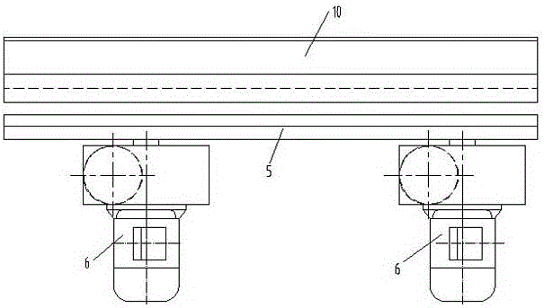
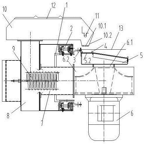
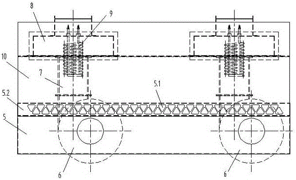
[0013] Embodiment 1: A pulp edge pre-drying device for knitted fabrics of a stenter setting machine, comprising a setting machine beam 1, a guide rail 2 arranged on the beam 1, a cloth clip needle plate 3 connected to the guide rail 2, and a clip needle plate 3 arranged on the cloth clip needle The cloth guide post 4 below the plate 3, the cloth edge 13 is clamped between the cloth guide post 4 and the cloth clip needle plate 3, a bracket 5 is arranged under the cloth guide post 4, and the bracket 5 is a sealed casing with a trapezoidal cross section. The upper surface 5.2 of the housing of the bracket 5 is evenly provided with triangular air return holes 5.1, and two fans 6 are arranged below the bracket 5, and the air return port 6.1 of the fan 6 is connected to the lower end surface of the housing of the bracket 5, and the air outlet 6.2 of the fan 6 passes through a The No. 1 air duct 7 is connected to the vertical No. 2 air duct 8, the No. 1 air duct 7 or the No. 2 air duc...


PUM


Abstract

A knitted fabric sized edge pre-drying device of a tentering setting machine comprises a setting machine beam, a guide rail arranged on the beam, a cloth clip-pin plate connected with the guide rail, and a cloth guide pillar arranged below the cloth clip-pin plate. The edge of cloth is clamped between the cloth guide pillar and the cloth clip-pin plate. A bracket is arranged below the cloth guide pillar and is a sealed shell with the section in a trapezoid shape, triangular air return holes are uniformly formed in the upper surface of the bracket shell, a plurality of fans are arranged below the bracket, air return ports of the fans are communicated with the lower end face of the bracket shell, air outlets of the fans are connected with vertical second air pipes through first air pipes, electric heating pipe heating devices are arranged in the first air pipes or the second air pipes, the second air pipes are connected with a cover above the setting machine beam, and air outlet holes are formed in the positions, right facing the air return holes in the bracket, of the cover. The knitted fabric sized edge pre-drying device is simple in structure, suitable for being installed on any setting machine and capable of effectively reducing the number of drying room sections and reducing input cost.

Description

technical field [0001] The invention relates to pretreatment equipment before a drying room of a setting machine, in particular to a pulp edge pre-drying device for knitted fabrics of a tenter setting machine. Background technique [0002] Since knitted fabrics are generally shaped by needle plates, but needle plate holes will be left on the edge of the fabric after the needle plate is set, generally printing and dyeing factories have to cut off the edge of the fabric with holes at the end of the machine. In order to prevent the fabric from curling, the printing and dyeing factory is convenient for cutting the edge of the fabric at the cloth outlet end. Generally, a starch edge device is installed at the cloth inlet end to sizing the fabric edge. . However, after the selvedge is sizing, there will be inconsistent dryness and humidity between the fabric surface and the selvage edge, which will make it difficult to control the setting time when the fabric is heated and set in...

Claims


Application Information

Patent Timeline
IPC IPC(8): D06B15/09D06B23/00
CPCD06B15/09D06B23/00
Inventor 张才南张盛周燕钱祖勤
Owner JIANGSU LITTLE SUN TECH DEV CO LTD
Why Eureka
Try Eureka