Rotating bracket used by a user for watching electronic screen in bed
A screen and electronic technology, applied in the direction of tables, bookshelves, bed tables, etc., can solve the problem of not fully meeting the requirements of use, and achieve the effects of improving blood circulation, joint correction and decompression
- Summary
- Abstract
- Description
- Claims
- Application Information
AI Technical Summary
Problems solved by technology
Method used
Image
Examples
example 1
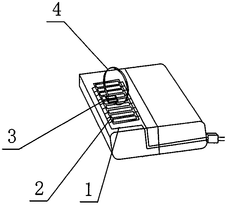
[0015] The rotating bracket is composed of a rotating control mechanism and a rotating mechanism. Such as figure 1 As shown, the rotation control mechanism includes a pillow control switch and a bed body position signal acquisition system. The pillow lifting control switch includes a bar-shaped test board 1, and several vertically arranged and horizontally arranged normally open reed switches 2 are connected in parallel. One row or two rows are fixed on the test board 1 .
[0016] The reed switches 2 are arranged alternately up and down on the test board 1 .
[0017] The width and arrangement length of the test board 1 and the reed switch 2 should be able to cover the activity space of the neck of the human body on the pillow. The distance between adjacent reed switches 2 should ensure that there is no blind area in the test range. The parallel lead of reed switch 2 is connected with the lifting control system of the lifting pillow body.
[0018] The bed position signal ac...
example 2
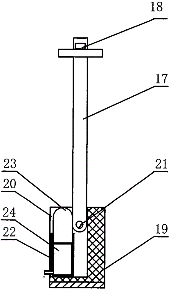
[0021] Such as figure 2 As shown, the rotation control mechanism in this example is a mechanical mechanism that is lowered by the gravity of the rotating rod and supported by the lifting slider to convert linear motion into rotary motion. The rotating part of the rotating device comprises a protruding rod 17 arranged horizontally and a rotating rod 18 vertically connected to it, and the end section of the protruding rod 17 is equipped with an electronic screen fixing frame 7 . The rotation control device is provided with a bracket seat 19, and the center area on the left side of the bracket seat 19 has a rectangular opening slot 20. The bottom end of the rotating rod 18 penetrates into the upper right side of the rectangular opening slot 20, and is realized in the rectangular opening slot 20 by the hinge shaft 21. 90 degree rotation in the vertical plane. The bottom of the rotating rod 18 is a semicircular arc concentric with the hinge shaft 21, and a rectangular cylinder 22...
example 3
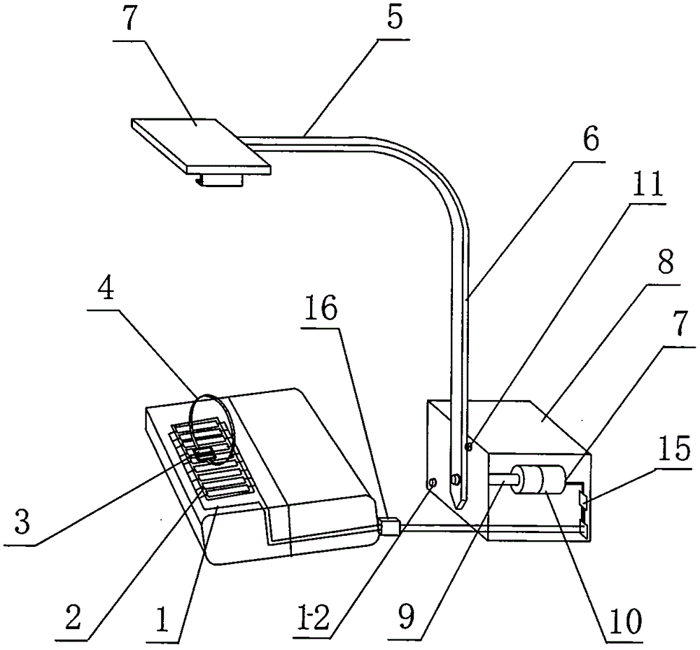
[0023] Such as image 3 As shown, the rotating mechanism is a rotating part bracket arm, which is composed of a horizontally arranged extending arm 5 and a rotating handle 6 vertically connected to it, and an electronic screen fixing frame 7 is installed at the end of the extending arm 5 .
[0024] The rotating pull mechanism is located in the rectangular rotary drive box 8, and the rotating shaft 9 is housed in it, and the front end of the rotating shaft 9 passes through the front box wall and protrudes outwards, and the bottom of the rotating handle 6 is fixed on its protruding end.
[0025] The rotary shaft 9 in the rotary drive box 8 is equipped with a reduction motor 10, the reduction motor 10 is provided with a motor forward and reverse switch 15, the bracket arm rotates clockwise when the reduction motor 10 rotates forward, and the bracket arm counterclockwise during reverse rotate. The switching mode of motor forward and reverse switch 15 is that the forward rotation ...
PUM
 Abstract
Description
Claims
Application Information
 - R&D
- Intellectual Property
- Life Sciences
- Materials
- Tech Scout
- Unparalleled Data Quality
- Higher Quality Content
- 60% Fewer Hallucinations
Browse by: Latest US Patents, China's latest patents, Technical Efficacy Thesaurus, Application Domain, Technology Topic, Popular Technical Reports.
© 2025 PatSnap. All rights reserved.Legal|Privacy policy|Modern Slavery Act Transparency Statement|Sitemap|About US| Contact US: help@patsnap.com


