a wire drawing machine
A wire drawing machine and body technology, which is applied in the field of wire drawing devices, can solve the problems that the tensile strength of the metal section of the wire does not meet the requirements, the tensile strength is affected, etc., and achieves good anti-vibration effect, improves strength and quality, and reduces space occupancy. Effect
- Summary
- Abstract
- Description
- Claims
- Application Information
AI Technical Summary
Problems solved by technology
Method used
Image

Examples
Embodiment 1
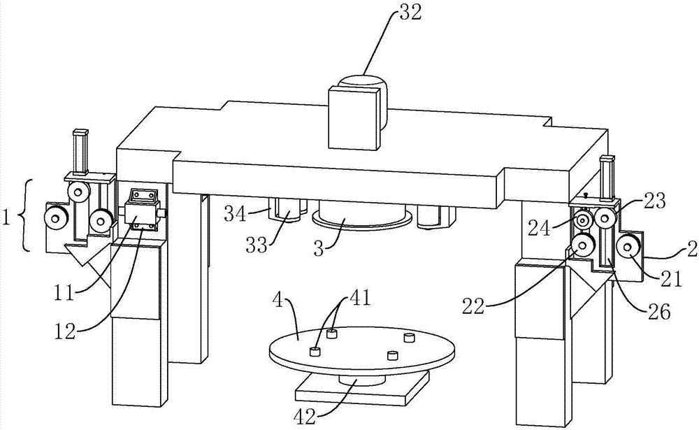
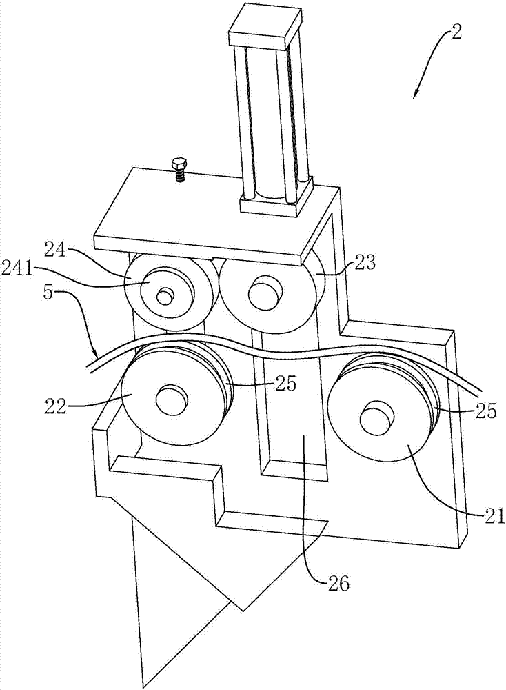
[0035] Embodiment 1: A wire drawing machine, including a peeling mechanism 2 and a wire feeding mechanism 1, wherein the peeling mechanism 2 includes a driving wheel 21, an auxiliary driving wheel 22, a pressing wheel 23 and a friction wheel for processing the wire 5 with impurities such as rust spots twenty four.
[0036]The wire feeding mechanism 1 and the peeling mechanism 2 are arranged on the same side of the wire drawing machine body, so the whole wire drawing machine body can be placed against the wall, which is equivalent to saving space and has a high space utilization rate. At the same time, the support of multiple surfaces can make the wire drawing machine The stability of the body is better, it is not easy to shake, and it is also convenient for users to observe and operate the peeling mechanism 2 and the wire feeding mechanism 1 at the same time; the two undertake different functions and perform different treatments on different wires 5, among which the peeling mec...
Embodiment 2
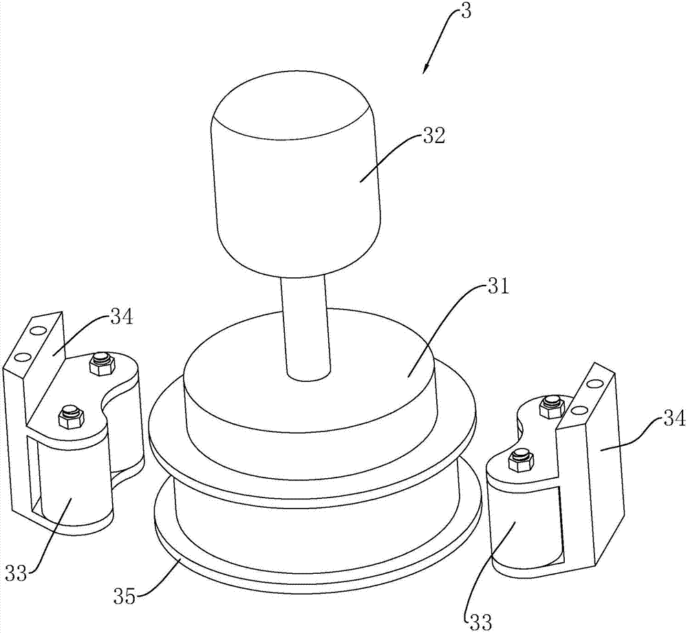
[0042] Embodiment 2: The difference from Embodiment 1 is that a circular wire take-up stand 4 is arranged below the coiling stand 31, and the axis line of the take-up stand 4 is the same as the axis line of the coiling stand 31. On the same straight line, the wires 5 fall from the coiling platform 31 and are collectively collected to the wire take-up rack 4, and the wire take-up rack 4 can quickly transfer and transport the collected wires 5. The take-up frame 4 is provided with a plurality of limit posts 41. During preheating processing, the wire 5 drawn out in advance is wound around the outer edge of the limit posts 41, which is convenient for the user to adjust the initial position of the wire 5. position. The winding diameter of the finished product after processing a section of wire rod 5 each time is relatively close, which is convenient for stacking and transportation of the wire rod 5 in the later stage. A support shaft 42 is provided at the lower end of the wire coi...
PUM
 Abstract
Description
Claims
Application Information
 - Generate Ideas
- Intellectual Property
- Life Sciences
- Materials
- Tech Scout
- Unparalleled Data Quality
- Higher Quality Content
- 60% Fewer Hallucinations
Browse by: Latest US Patents, China's latest patents, Technical Efficacy Thesaurus, Application Domain, Technology Topic, Popular Technical Reports.
© 2025 PatSnap. All rights reserved.Legal|Privacy policy|Modern Slavery Act Transparency Statement|Sitemap|About US| Contact US: help@patsnap.com