Movable machine tool

A technology of machine tools and planers, applied in the field of pipeline processing equipment, to achieve the effects of ensuring processing safety, reducing equipment costs, and saving procedures

Inactive Publication Date: 2016-09-21
王兴鼎
View PDF0 Cites 0 Cited by
  • Summary
  • Abstract
  • Description
  • Claims
  • Application Information

AI Technical Summary

Problems solved by technology

[0003] The purpose of the present invention is to propose a mobile machine tool capable of fast and accurate cutting, chamfering and grooving at the same time, so as to solve the existing problem of using multiple machine tools to complete pipeline processing manually and in multiple steps

Method used


Image

  • Movable machine tool
  • Movable machine tool
  • Movable machine tool

Examples


Embodiment Construction

[0033] The present invention will be described in detail below in conjunction with specific embodiments shown in the accompanying drawings. However, these embodiments do not limit the present invention, and any structural, method, or functional changes made by those skilled in the art according to these embodiments are included in the protection scope of the present invention.

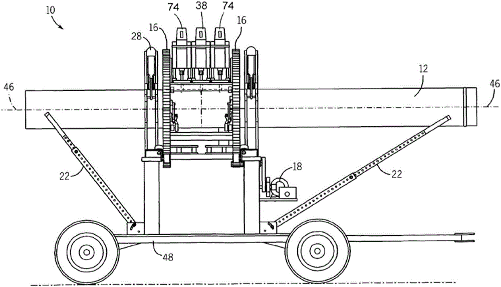
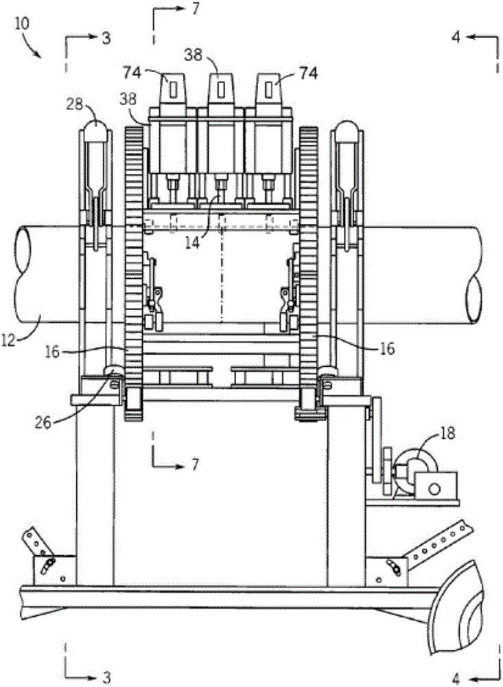
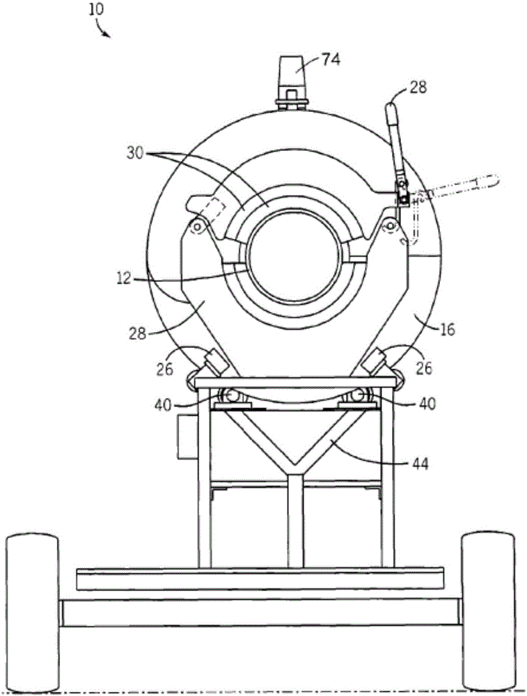
[0034] refer to Figure 1-13a A kind of mobile machine tool 10 shown is used for simultaneously cutting, chamfering, slotting to pipeline, described mobile machine tool comprises a support 48, at least one pipe clamp 28 is fixed on the support 48, and described pipe clamp 28 locates a main shaft 46, the separating carriage 16 is rotatably fixed on the bracket 48 and connected with the pipe clamp 28, a router 38 is fixed on the separating carriage 16, and the router 38 includes a chamfering cutting unit 14, a The router 74 for digging is fixed on the bracket 48, and a driving motor 18 is used to rotate...


PUM


Abstract

The invention provides a movable machine tool. The movable machine tool comprises a support. At least one pipe clamp is fixed to the support. The pipe clamp is used for positioning a spindle used for fixing a pipe. A separable sliding rack is rotatably fixed to the support and connected with the pipe clamp. A compass planing machine is fixed to the separable sliding rack and comprises a chamfer cutting unit. A rabbet planing machine is installed on the separable sliding rack and comprises a rabbet planing unit. The position of the rabbet planing machine can be adjusted. A driving motor drives the separable sliding rack to rotate. The separable sliding rack drives the compass planing machine and the rabbet planing machine to rotate around the pipe at the same time. According to the movable machine tool, the pipe can be cut, chamfered and grooved at the same time through one step, the number of procedures is reduced, the working efficiency is improved, and the safety performance is higher. In addition, multiple steps can be completed only through one machine tool, and the equipment cost is reduced.

Description

technical field [0001] The invention relates to the technical field of pipeline processing equipment, in particular to a mobile machine tool. Background technique [0002] In the prior art pipe processing technology, the pipe is generally segmented by manual cutting, and the end of the pipe is chamfered by a chamfering machine tool, and then the segmented pipe is grooved by a grooving machine tool. The whole process includes multiple processes, and the method of manual cutting and chamfering has obvious shortcomings compared with the automatic method in essence. Therefore need a kind of improved equipment to gather above-mentioned three processes and finish on a lathe. When processing longer tubes or hoses, the length of existing machine tools must not be adjusted, and the tubes cannot be fixed well to complete the processing process, or the tubes need to be fixed by manual support at both ends of the tubes, which wastes manpower. When the tube is processed and released, t...

Claims


Application Information

Patent Timeline
IPC IPC(8): B23P23/02
CPCB23P23/02
Inventor 王兴鼎
Owner 王兴鼎
Why Eureka
Try Eureka