Grinding machine

A grinding machine, cylindrical technology, applied in the direction of grinding workpiece support, etc., can solve the problems of reduced grinding efficiency, poor grinding quality, strong fatigue, etc., to achieve the effect of improving work efficiency, improving grinding quality, and high replacement efficiency

Inactive Publication Date: 2016-09-21
SUZHOU BOLAIXI ELECTRICAL APPLIANCE CO LTD
View PDF8 Cites 4 Cited by
  • Summary
  • Abstract
  • Description
  • Claims
  • Application Information

AI Technical Summary

Problems solved by technology

[0002] Grinding machines are widely used in the finishing and surface polishing of workpieces. The existing grinding machines include fixed grinding machines and mobile grinding machines. The fixed grinding machine is fixed on the base, and then the workpiece is placed on the grinding wheel for grinding. However, the existing The fixed grinding machine cannot adjust the distance between the workpiece and the grinding wheel, and cannot adjust the pressure, resulting in poor grinding quality, narrow application range, and high cost
The mobile grinding machine is manually held in the hand to grind the workpiece. As time goes on, the hand will be sore and fatigued, which will reduce the grinding efficiency. At the same time, there may be accidents, which is very unsafe.

Method used


Image

  • Grinding machine

Examples


Embodiment Construction

[0014] The present invention will now be further described in detail in conjunction with the accompanying drawings and embodiments. These drawings are all simplified schematic diagrams, only illustrating the basic structure of the present invention in a schematic manner, so it only shows the composition related to the present invention.

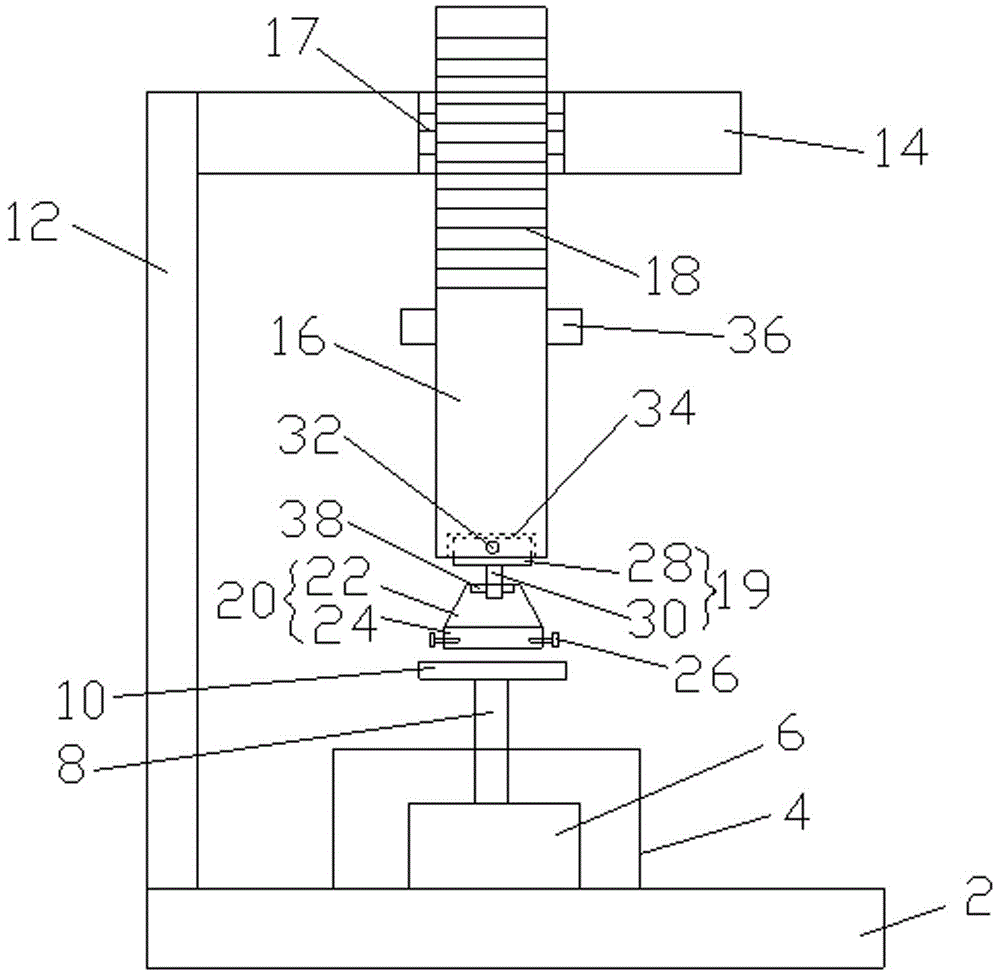
[0015] Such as figure 1 As shown, a grinding machine includes a base 2, a grinding machine body 4 installed on the base 2, a motor 6 is arranged in the grinding machine body 4, and an output shaft 8 of the motor 6 extends out of the grinding machine body 4 and a grinding wheel is fixed on it. 10. A bracket is fixed on the base 2. The bracket includes a vertical rod 12 and a horizontal rod 14. The horizontal rod 14 is threadedly connected with a vertical rod 16. The bottom end is detachably connected with a clamping assembly, and the clamping assembly includes a support 19, a clamping seat 20 connected with the support 19, and the clamping sea...


PUM


Abstract

The invention relates to a grinding machine which comprises a base and a grinding machine body installed on the base. A motor is arranged in the grinding machine body. An output shaft of the motor stretches out of the grinding machine body, and a grinding wheel is fixed to the output shaft of the motor. A support is fixed to the base and comprises a vertical rod and a horizontal rod. The horizontal rod is in threaded connection with a stand rod. The bottom end of the stand rod is detachably connected with a clamp assembly. The clamp assembly comprises a support seat and a clamp seat connected with the support seat. The clamp seat comprises a circular truncated cone shaped seat and a barrel-shaped seat which are integrally formed and arranged up and down. At least two adjusting bolts are arranged on the circumference of the barrel-shaped seat. According to the grinding machine, a workpiece is installed in the barrel-shaped seat, and the height of the stand rod can be adjusted by rotating the stand rod, so that pressure between the workpiece and the grinding wheel is adjusted to guarantee the smooth proceeding of grinding. The outer diameter of a first cylindrical seat is greater than that of a second cylindrical seat; when the workpiece in the barrel-shaped seat needs to be replaced, the first cylindrical seat is supported by a replacement platform by rotating the barrel-shaped seat, supporting is stable and firm, and shaking is avoided.

Description

technical field [0001] The invention relates to an electric tool, in particular to a grinding machine. Background technique [0002] Grinding machines are widely used in the finishing and surface polishing of workpieces. The existing grinding machines include fixed grinding machines and mobile grinding machines. The fixed grinding machine is fixed on the base, and then the workpiece is placed on the grinding wheel for grinding. However, the existing The fixed grinding machine cannot adjust the distance between the workpiece and the grinding wheel, and cannot adjust the pressure, so that the grinding quality is poor, the application range is narrow, and the cost is high. The mobile grinding machine is manually held in the hand to grind the workpiece. As time goes on, the hand will be sore and fatigued, which will reduce the grinding efficiency. At the same time, there may be accidents, which is very unsafe. Contents of the invention [0003] The invention overcomes the sho...

Claims


Application Information

Patent Timeline
Patent Type & Authority Applications(China)
IPC IPC(8): B24B41/06
CPCB24B41/06
Inventor 徐超
Owner SUZHOU BOLAIXI ELECTRICAL APPLIANCE CO LTD
Why Eureka
Try Eureka