Strong permanent magnetic water treatment equipment and application

A water treatment equipment and permanent magnet technology, which is applied in the fields of magnetic field/electric field water/sewage treatment, natural water treatment, water/sewage treatment, etc. It can solve the problem of unreasonable distribution of magnetic force lines, improper arrangement of permanent magnets, and the inability of magnetic fields to cover the transverse direction of pipes. Cross-section and other problems, to achieve good magnetic treatment effect, solve scaling, and improve the effect of

Inactive Publication Date: 2016-09-21
NORTH CHINA ELECTRIC POWER UNIV (BAODING)
View PDF4 Cites 1 Cited by
  • Summary
  • Abstract
  • Description
  • Claims
  • Application Information

AI Technical Summary

Problems solved by technology

At present, there are some related equipment on the market for magnetic treatment, but there are many problems: (1) At present, most of the strong permanent magnetic water treatment equipment is only suitable for small pipe diameters. For example, there is a gap in the application of condenser pipes in thermal power plants. The traditional design makes it impossible for the magnetic field to cover the entire cross-section of the pipe
(2) If the magnetic water processor wants to achieve the best treatment effect, it is necessary to ensure that the magnetic force line is perpendicular to the flow direction of the water. However, the improper arrangement of the permanent magnets of some current magnetic water processors makes the distribution of the magnetic force line unreasonable.
The above-mentioned deficiencies make the water treatment effect of the magnetic processor unsatisfactory

Method used


Image

  • Strong permanent magnetic water treatment equipment and application
  • Strong permanent magnetic water treatment equipment and application
  • Strong permanent magnetic water treatment equipment and application

Examples


Embodiment 1

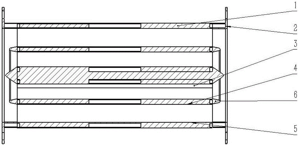
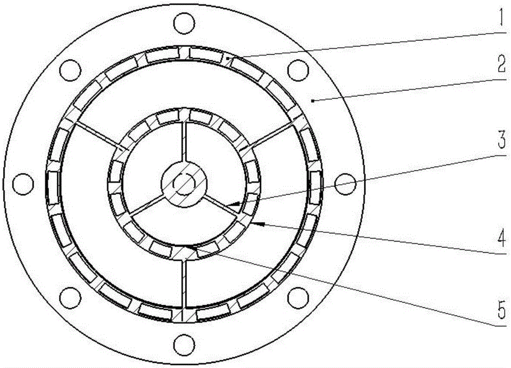
[0028] Such as figure 1 As shown, the middle of the strong permanent magnet water treatment equipment is a column, which adopts a multi-layer casing 5 structure, and the distance between each layer of casing is not more than 300mm; the column and the inner layer of casing are welded and connected by three brackets 3 , three brackets 3 are welded and connected between adjacent two layers of casing 5; flanges 2 are also installed at both ends of the casing 5 wall, and two rows of casings are installed on the surface of each layer of casing 5 along the direction of the pipe axis NdFeB strong permanent magnet 1, the NdFeB permanent magnet can be installed on the outside of the casing or on the inside of the casing; the arc length between two adjacent rows of NdFeB permanent magnets on the same arc is not less than 20mm; and a waterproof partition 4 and a spoiler 6 are also installed outside each layer of NdFeB strong permanent magnet 1. The turbulence device can ensure the smooth...

Embodiment 2

[0033] In order to verify that the magnetic field distribution adopted in the present invention has a better magnetic treatment effect, the applicant conducted a comparative analysis and measured the scale inhibition effect under two different magnetic field distributions.

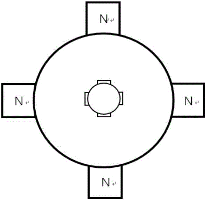
[0034] image 3 For the magnetic field distribution that the present invention adopts (lines of force can be perpendicular to the flow direction of water), Figure 4 It is the magnetic field distribution used by most magnetic water processors at present (the magnetic field lines cannot be perpendicular to the flow direction of water), among which image 3 The outer magnetic poles of the four magnets in the middle column are all S. The scale inhibition rate distribution curves of two different magnetic field distributions at various pH and flow rates are as follows: Figure 5 , Figure 6 shown.

[0035] From Figure 5 , Figure 6 It can be seen that under various pH and flow rate conditions, image 3...


PUM

PropertyMeasurementUnit
lengthaaaaaaaaaa
diameteraaaaaaaaaa
thicknessaaaaaaaaaa

Abstract

The invention belongs to the field of optimal treatment of circulating water systems of thermal power plants, and particularly relates to strong permanent magnetic water treatment equipment and application. An upright post is arranged in middle of the equipment, a multilayer sleeve structure is adopted, the upright post is connected with an inner-layer sleeve through three brackets in a welding manner, every two adjacent layers of sleeves are connected through the three brackets in the welding manner, two rows of neodymium iron boron strong permanent magnets are mounted on the surface of each layer of sleeve in the direction of a pipeline shaft, and a waterproof baffle plate and a turbulence device are mounted outside the neodymium iron boron strong permanent magnets of each layer. The strong permanent magnetic water treatment equipment can be used for scale prevention, corrosion prevention, sterilization and algae removal of a circulating cooling water pipeline of a thermal power plant.

Description

technical field [0001] The invention belongs to the field of optimized treatment of circulating water systems in thermal power plants, and in particular relates to strong permanent magnet water treatment equipment and its application. Background technique [0002] The circulating water cooling system is an important part of the thermal power plant. However, the circulating cooling water pipelines often face problems such as scaling, corrosion and microbial growth, which seriously affect the safe and efficient operation of the circulating water system. At present, to address these problems, the main method used by power plants is chemical method, that is, adding scale inhibitors, corrosion inhibitors and bactericides and algaecides. These methods will pollute the environment on the one hand, and will increase the cost on the other hand. The circulating water system is treated by using a magnetic field. The equipment is simple, easy to maintain, and will not pollute the envir...

Claims


Application Information

Patent Timeline
Patent Type & Authority Applications(China)
IPC IPC(8): C02F1/48
CPCC02F1/481C02F2103/023
Inventor 马志勇王罡张杰曹晟磊
Owner NORTH CHINA ELECTRIC POWER UNIV (BAODING)
Why Eureka
Try Eureka