A microgravity suspension centrifugal spinning method

A centrifugal spinning and centrifugal spinning technology, applied in textiles and papermaking, filament/thread forming, fiber processing, etc., can solve problems such as low safety, low efficiency, discontinuous fibers, etc., and achieve the effect of avoiding high energy consumption

Active Publication Date: 2018-02-02
WUHAN TEXTILE UNIV
View PDF8 Cites 0 Cited by
  • Summary
  • Abstract
  • Description
  • Claims
  • Application Information

AI Technical Summary

Problems solved by technology

However, due to the existence of static electricity, the centrifugal spinning technology based on electrostatic collection has disadvantages such as high energy consumption and low safety.
[0006] To sum up, the centrifugal spinning based on annular collection is a two-step centrifugal spinning method in which the fibers are first spun on the receiving columns annularly distributed around the centrifugal spinning tank, and then collected by airflow. The fibers obtained are discontinuous short fibers, and the efficiency is low; the fibers obtained by the centrifugal spinning method based on electrostatic collection are still discontinuous, and the whole process is accompanied by high-voltage static electricity, resulting in high energy consumption, low safety factor, and low efficiency

Method used


Image

  • A microgravity suspension centrifugal spinning method

Examples


Embodiment 1

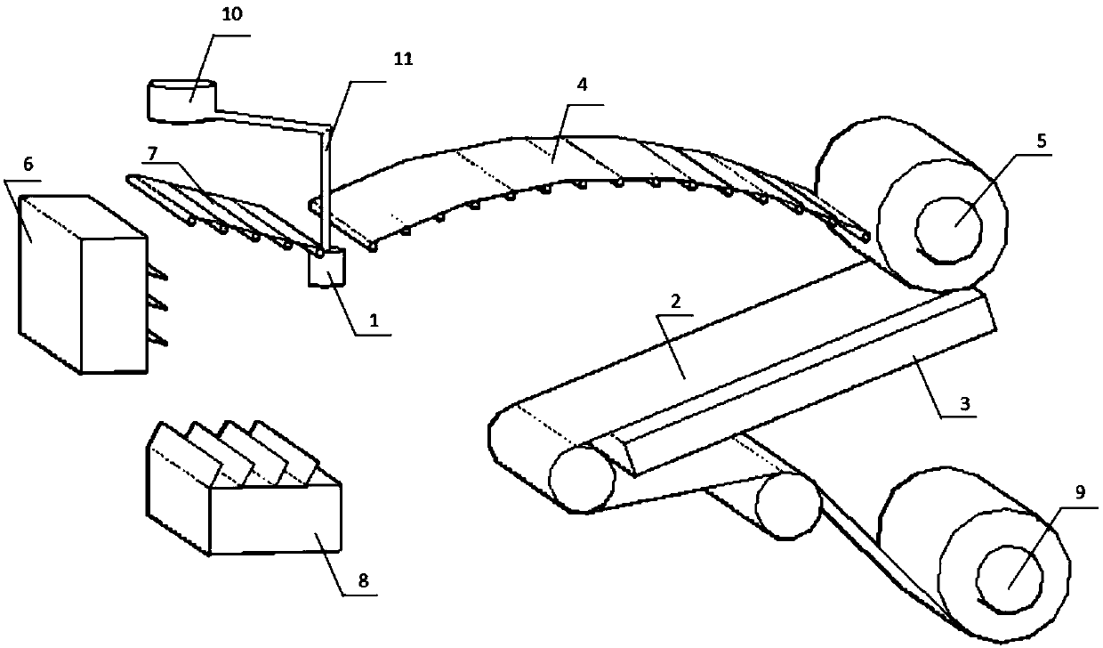
[0025] During centrifugal spinning, the angle between the cloth guide belt of the fiber collection device and the plane at the bottom of the centrifugal spinning tank is 5°, and the straight line between the center point of the cloth guide belt and the center point of the bottom of the centrifugal spinning tank The distance is 50cm, the width of the cloth guide belt of the fiber collection device is 40cm, a negative pressure generator is installed under the cloth guide belt, the suction port of the negative pressure generator is set opposite to the lower surface of the cloth guide belt, The distance between the lower surfaces is 1cm, and the air volume of the negative pressure generator is 200m 3 / h, between the centrifugal spinning pot and the fiber collection device, a first temperature control plate with a radian of 0.04rad is set, the width of the first temperature control plate is 50cm, and the lower surface of the first temperature control plate is arranged parallel to ea...

Embodiment 2

[0027] During centrifugal spinning, the angle between the cloth guide belt of the fiber collection device and the plane at the bottom of the centrifugal spinning tank is 40°, and the straight line between the center point of the cloth guide belt and the center point of the bottom of the centrifugal spinning tank The distance is 150cm, the width of the cloth guide belt of the fiber collection device is 100cm, a negative pressure generator is installed under the cloth guide belt, the suction port of the negative pressure generator is set opposite to the lower surface of the cloth guide belt, The distance between the lower surfaces is 1cm, and the air volume of the negative pressure generator is 500m 3 / h, between the centrifugal spinning pot and the fiber collection device, a first temperature control plate with a radian of 0.08rad is set, the width of the first temperature control plate is 110cm, and the lower surface of the first temperature control plate is arranged parallel t...

Embodiment 3

[0029] During centrifugal spinning, the angle between the guide belt of the fiber collection device and the plane where the bottom of the centrifugal spinning tank is located is 25 。 , the straight-line distance between the central point of the cloth guide belt and the center point of the bottom of the centrifugal spinning tank is 100cm, the width of the cloth guide belt of the fiber collection device is 70cm, and a negative pressure generator is set under the cloth guide belt to generate negative pressure. The air suction port of the device is set opposite to the lower surface of the cloth guide belt, the distance between the air suction port and the lower surface of the cloth guide belt is 1cm, and the air volume of the negative pressure generator is 350m 3 / h, between the centrifugal spinning tank and the fiber collection device, a first temperature control plate with a radian of 0.06rad is set, the width of the first temperature control plate is 80cm, and the lower surface ...


PUM

PropertyMeasurementUnit
diameteraaaaaaaaaa

Abstract

The invention relates to a micro-gravity suspension type centrifugal spinning method, and belongs to the technical field of spinning. The micro-gravity suspension type centrifugal spinning method comprises the following steps: arranging a fiber collecting device and a first temperature control board in front of a centrifugal spinning tank; arranging a main air flow generator and a second temperature control board at the rear of the centrifugal spinning tank; arranging a secondary air flow generator below the second temperature control board; arranging a negative pressure generator below the fiber collecting device so that a centrifugal spinning air flow channel which is in a parabolic path is formed between the centrifugal spinning tank and the fiber collecting device; running jet flow which is sprayed out from the centrifugal spinning tank in the centrifugal spinning air flow channel in a micro-gravity suspension station to the direction of the fiber collecting device; gradually solidifying the jet flow into continuous filaments under the thermal radiation effect of the first temperature control board and the second temperature control board; and finally uniformly and continuously spreading the continuous filaments on the fiber collecting device to form a continuous filament net. The micro-gravity suspension type centrifugal spinning method is high in spinning efficiency, simple in equipment, easy to operate and extensive in raw materials.

Description

technical field [0001] The invention relates to a microgravity suspension type centrifugal spinning method, which belongs to the technical field of textiles. Background technique [0002] The principle of centrifugal spinning is: use the centrifugal force generated by the high-speed rotating spinneret to throw the spinning solution or melt out of the nozzle and generate an initial jet, which is then stretched and solidified to form ultrafine fibers. [0003] The fiber forming process in centrifugal spinning can usually be divided into the following three stages: the generation of the initial jet source, the drafting and solidification of the jet, and the collection of fibers. Among them, the first stage determines whether the spinning can be carried out normally, which is the first premise of centrifugal spinning; the second stage determines the shape and performance of fibers, which is the most critical stage in centrifugal spinning; the third stage is mainly responsible fo...

Claims


Application Information

Patent Timeline
Patent Type & Authority Patents(China)
IPC IPC(8): D01D5/18
CPCD01D5/18
Inventor 徐卫林刘欣杨锴张科李文斌夏治刚邓波吴龙涛宋宝祥陈利军
Owner WUHAN TEXTILE UNIV
Why Eureka
Try Eureka