Steel beam segment, continuous combined beam bridge and construction method of continuous combined beam bridge

A construction method and technology of steel girder sections, applied in bridges, bridge parts, bridge materials, etc., can solve the problems of large internal force shared by steel beams, poor bridge structure economy, and increase engineering costs, and achieve high concrete compressive capacity and concrete. The effect of high compressive strength and improved performance

Active Publication Date: 2016-09-21
CHINA MAJOR BRIDGE ENERGINEERING
View PDF5 Cites 2 Cited by
  • Summary
  • Abstract
  • Description
  • Claims
  • Application Information

AI Technical Summary

Problems solved by technology

Composite girder bridges generally adopt cantilever construction. During the construction process, the concrete deck of the upper flange of the composite girder bridge is pulled and closed to form a bridge. The force is extremely unfavorable, making it easy to crack, and the width of the crack is difficult to control, which has a negative impact on the structural durability of the beam bridge and the overall bridge, and it is difficult to give full play to the advantages of the strong compressive capacity of the composite beam concrete bridge deck
[0003] At present, the commonly used methods to solve such pr

Method used


Image

  • Steel beam segment, continuous combined beam bridge and construction method of continuous combined beam bridge
  • Steel beam segment, continuous combined beam bridge and construction method of continuous combined beam bridge
  • Steel beam segment, continuous combined beam bridge and construction method of continuous combined beam bridge

Examples


Embodiment Construction

[0032] The present invention will be described in further detail below in conjunction with the accompanying drawings.

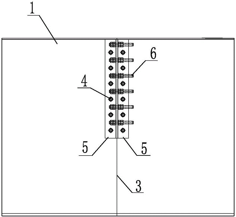
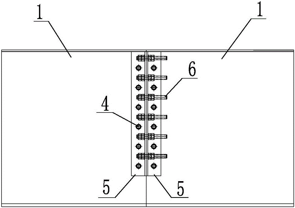
[0033] The present invention provides a steel beam segment. The steel beam segment 1 includes two parts, a left and a right, and a gap 3 is formed between the left and right parts, and the left and right parts are connected by welding.

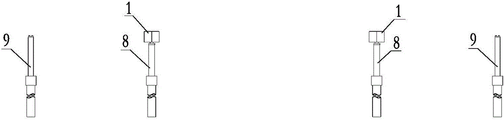
[0034] The present invention also provides a continuous composite girder bridge, such as Figure 4 As shown, the girder bridge includes two side piers 9 and at least one middle pier 8 between the two side piers 9 , the specifications of the girder bridge are different, and the number of piers 8 is also different. The pier top of the middle pier 8 is provided with a steel beam section 1. The steel beam section 1 includes two parts on the left and right, and there is a gap 3 formed between the left and right parts, and the left and right parts are connected by welding. The gap 3 is connected with the The centerlines of the mid...


PUM


Abstract

The invention relates to the field of beam bridge construction and discloses a steel beam segment. The steel beam segment comprises a left part and a right part. A gap formed in an opposite-pulling manner is formed between the left part and the right part. The left part and the right part are connected in a welded manner. A continuous combined beam bridge comprises two abutment piers and at least one middle pier located between the two abutment piers. The pier top of the middle pier is provided with the steel beam segment. Multiple combined beam segments are arranged on the two sides of the steel beam segment. A construction method of the continuous combined beam bridge includes the following steps that firstly, the steel beam segment formed by splicing the left part and the right part is provided, the left part and the right part of the steel beam segment are connected through bolts, and the bolts are tensioned; secondly, the combined beam segments are installed on the two sides of the steel beam segment till a steel beam is closed; and thirdly, the bolts on the steel beam segments are loosened gradually, and the left part and the right part of the steel beam segment are welded. By the adoption of the steel beam segment, the continuous combined beam bridge, and the construction method of the continuous combined beam bridge, the working performance of a concrete bridge panel can be greatly improved.

Description

technical field [0001] The invention relates to the field of bridge construction, in particular to a steel girder segment, a continuous composite beam bridge and a construction method for a continuous composite beam bridge. Background technique [0002] Composite girder bridge refers to the connection of steel girder and concrete bridge deck as a whole through shear connectors. It is a bridge structure that makes both of them work together. features. Composite girder bridges generally adopt cantilever construction. During the construction process, the concrete deck of the upper flange of the composite girder bridge is pulled and closed to form a bridge. Extremely unfavorable stress makes it very easy to crack, and the width of the crack is difficult to control, which has a negative impact on the structural durability of the beam bridge and the overall bridge, and it is difficult to give full play to the advantages of the strong compressive capacity of the composite beam con...

Claims


Application Information

Patent Timeline
IPC IPC(8): E01D1/00E01D19/00E01D19/12E01D21/00E01D101/30
CPCE01D1/00E01D19/00E01D19/125E01D21/00E01D2101/30
Inventor 颜兆福罗扣肖海珠张强高宗余王为玉张兴志李少骏孙立山付岚岚别业山胡文军唐斌
Owner CHINA MAJOR BRIDGE ENERGINEERING
Why Eureka
Try Eureka