Prefabricated cover beam steel bar jig frame and manufacturing method of prefabricated cover beam reinforcement cage

A technology of reinforcing steel cages and covering beams, applied in bridges, bridge parts, bridge construction and other directions, can solve the problems of low installation accuracy of steel bars, unguaranteed thickness of protective layer, and difficult to control the positioning of steel bars and end grouting sleeves. Achieve the effect of improving production accuracy and speed

Active Publication Date: 2016-09-21
SHANGHAI NO 4 CONSTR +1
View PDF5 Cites 12 Cited by
  • Summary
  • Abstract
  • Description
  • Claims
  • Application Information

AI Technical Summary

Problems solved by technology

[0004] However, the inventors of the present invention have found that in the production of existing prefabricated cap beams, the main reinforcement and stirrups are all manually installed when the cap beam steel bars are bound, making it difficult to control the posit...

Method used


Image

  • Prefabricated cover beam steel bar jig frame and manufacturing method of prefabricated cover beam reinforcement cage
  • Prefabricated cover beam steel bar jig frame and manufacturing method of prefabricated cover beam reinforcement cage
  • Prefabricated cover beam steel bar jig frame and manufacturing method of prefabricated cover beam reinforcement cage

Examples


Embodiment 1

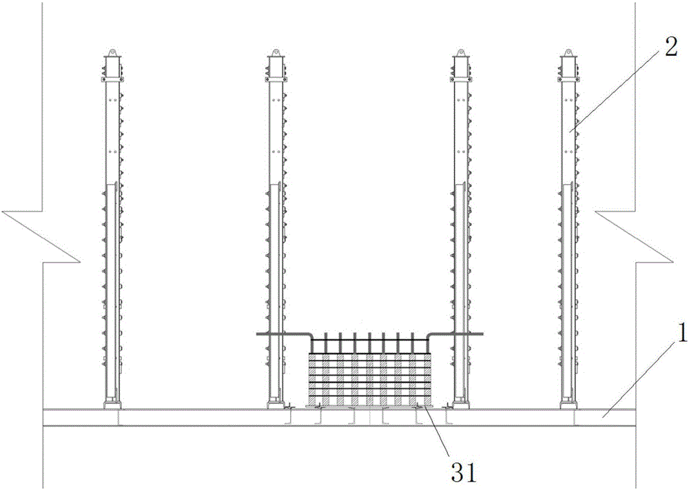
[0052] This embodiment provides a prefabricated cover beam steel tire frame, which is used in the prefabricated cover beam manufacturing process for accurately positioning the steel bars and end pre-embedded grouting sleeves in the prefabricated cover beam reinforcement cage. Such as figure 1 As shown, the prefabricated cap beam steel tire frame in this embodiment includes: an underframe 1 , a plurality of positioning frames 2 and a grouting sleeve positioning plate 31 . Among them, the underframe 1 is used to ensure the stability of the prefabricated cap beam reinforced tire frame system. The positioning frame 2 is provided with a main reinforcement positioning structure for accurately positioning the main reinforcement in the reinforcement cage of the prefabricated cover beam. The grouting sleeve positioning plate 3 is arranged on the underframe 1, and is used for positioning the end grouting sleeve of the prefabricated cover beam reinforcement cage.

[0053]The prefabrica...

Embodiment 2

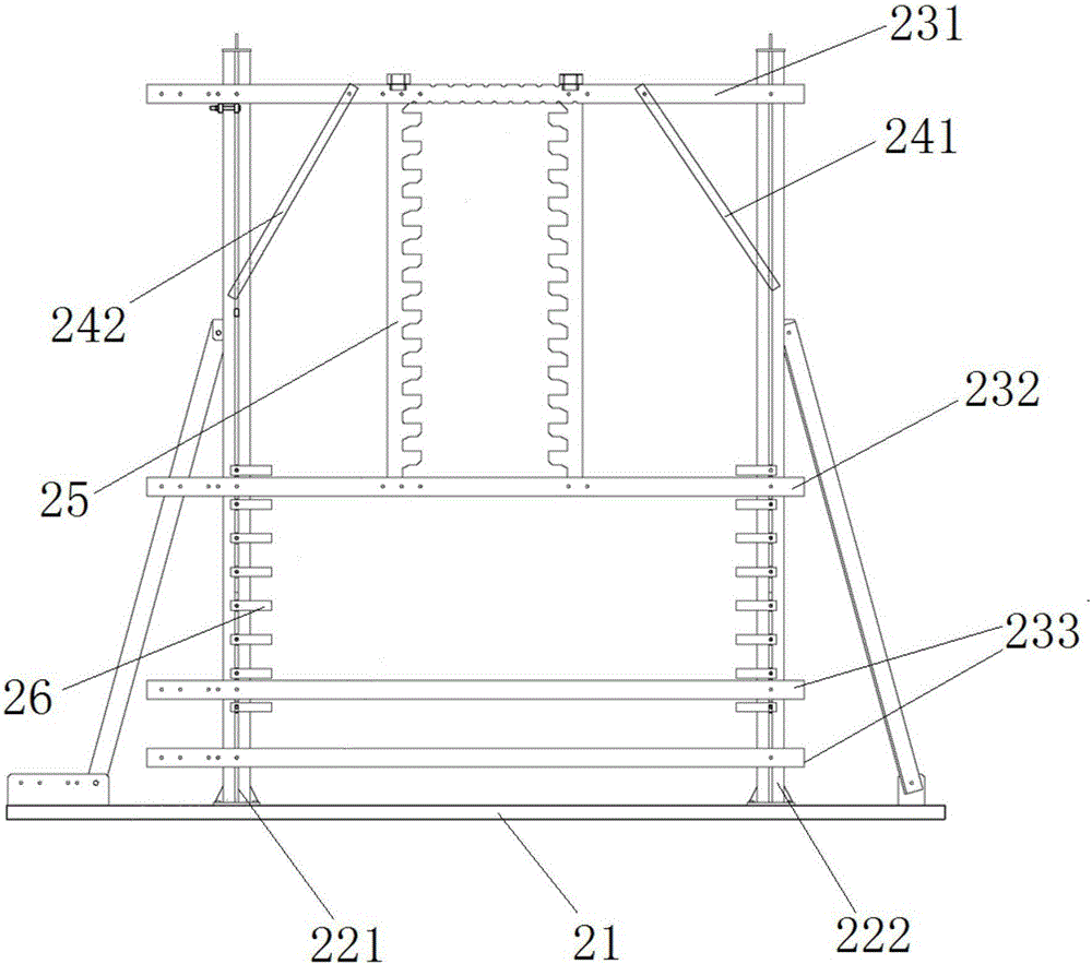
[0056] Preferably, this embodiment provides a prefabricated cap beam reinforced tire frame, compared with the previous embodiment, such as figure 2 As shown, the positioning frame of the prefabricated cap beam steel frame of this embodiment includes: supporting beams 21, columns and beams. Wherein, the supporting beam 21 is connected on the chassis. The columns are arranged on the supporting beams 21 . The uprights are preferably double uprights with diagonal braces, specifically, the uprights include first uprights 221 and second uprights 222 oppositely arranged. One end of the beam is connected to the first column 221 , and the other end is connected to the second column 222 . Wherein, the beam includes an upper beam 231 , a middle beam 232 and a lower beam 233 . The upper beam 231 is connected with the upper ends of the first column 221 and the second column 222 (that is, located at the upper part of the positioning frame); the lower beam 233 is connected with the lower...

Embodiment 3

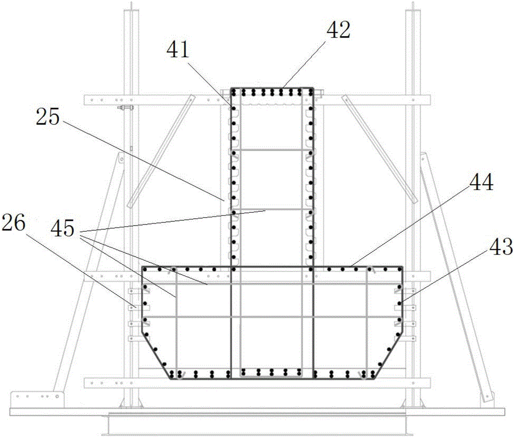
[0060] Preferably, this embodiment provides a prefabricated cap beam reinforced tire frame, compared with the above embodiments, such as figure 2 with image 3 As shown, the main reinforcement positioning structure includes a first main reinforcement positioning structure for positioning the upper main reinforcement 41 in the reinforcement cage of the prefabricated cover beam. Wherein, the first main reinforcement positioning structure includes a hanging plate 25, the hanging plate 25 is located between the first column 221 and the second column 222, and the upper end of the hanging plate 25 is fixed to the upper beam 231, and the lower end is fixed to the middle beam 232. A plurality of first positioning grooves are longitudinally arranged on the hanging plate 25 for positioning the upper main reinforcement vertically distributed in the reinforcement cage of the prefabricated cover beam. The number of hanging plates can be selected according to the shape of the prefabricate...


PUM


Abstract

The invention relates to a prefabricated cover beam steel bar jig frame and a manufacturing method of a prefabricated cover beam reinforcement cage and belongs to the technical field of bridge structure construction. According to the main technical scheme, the prefabricated cover beam steel bar jig frame comprises an underframe, a plurality of positioning frames and a grouting sleeve positioning disc; the multiple positioning frames are distributed on and connected to the underframe; main reinforcement positioning structures are arranged on the positioning frames and used for positioning main reinforcements in the prefabricated cover beam reinforcement cage; and the grouting sleeve positioning disc is arranged on the underframe and used for positioning an end grouting sleeve of the prefabricated cover beam reinforcement cage. The manufacturing method of the prefabricated cover beam reinforcement cage comprises the step that the prefabricated cover beam reinforcement cage is manufactured through the prefabricated cover beam steel bar jig frame. The prefabricated cover beam steel bar jig frame and the manufacturing method of the prefabricated cover beam reinforcement cage are mainly used for precisely positioning steel bars and the embedded end grouting sleeve of the prefabricated cover beam reinforcement cage, and the splicing precision and manufacturing quality of the prefabricated cover beam reinforcement bars are effectively improved.

Description

technical field [0001] The invention relates to the technical field of bridge structure construction, in particular to a method for manufacturing a prefabricated cover beam reinforcement frame and a prefabricated cover beam reinforcement cage. Background technique [0002] With the promotion and popularization of prefabricated assembly technology in urban bridges, the steel sleeve grouting connection technology has been widely used in the vertical connection of prefabricated concrete components such as prefabricated columns and prefabricated cap beams. During the implementation process, the grouting sleeve is pre-embedded at the end of the precast concrete member; when connecting vertically, insert steel bars into the grouting sleeve, and fill the sleeve slurry for connection, and use the gripping force of the tank slurry after hardening Realize the force transmission between the steel bar and the sleeve. [0003] The concrete prefabricated cover beam plays the role of supp...

Claims


Application Information

Patent Timeline
IPC IPC(8): E01D19/00E01D21/00E04C5/06E04C5/16E04G21/12
CPCE01D19/00E01D21/00E04C5/06E04C5/162E04G21/12
Inventor 张杲刘经熠干华铭查义强姜海西汪小林陈实
Owner SHANGHAI NO 4 CONSTR
Why Eureka
Try Eureka