Turbo molecular pump

A turbomolecular pump and stator technology, applied in the direction of pumps, pump components, axial flow pumps, etc., can solve the problems of easy accumulation of reaction products, increased speed, and temperature exceeding the allowable temperature.

Active Publication Date: 2016-09-21
SHIMADZU SEISAKUSHO CO LTD
View PDF6 Cites 3 Cited by
  • Summary
  • Abstract
  • Description
  • Claims
  • Application Information

AI Technical Summary

Problems solved by technology

[0003] However, when a large amount of gas is discharged, there is a concern that the temperature of the rotor (rotor) including the moving blade may exceed the allowable temperature
If the temperature of the rotor exceeds the allowable temperature, there is a concern that the speed of expansion due to creep will increase, and the rotor will come into contact with the stator (stator) in a shorter time than the design life.
[0004] Moreover, in such a semiconductor manufacturing device, reaction products are generated during etching or CVD, and the reaction products tend to accumulate in the threaded stator of the threaded groove pump part.

Method used


Image

  • Turbo molecular pump
  • Turbo molecular pump
  • Turbo molecular pump

Examples


Embodiment Construction

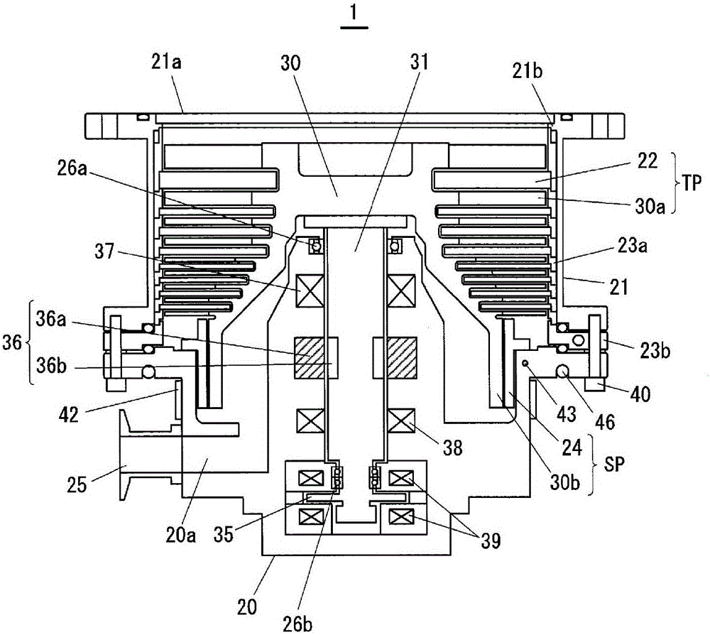
[0060] Hereinafter, modes for implementing the present invention will be described with reference to the drawings. figure 1 It is a figure which shows the schematic structure of the turbomolecular pump of this invention. Turbomolecular pumps include figure 1 The shown pump body 1 and a control unit (control unit) (not shown) for driving and controlling the pump body 1 . In the control unit, there are provided a main control unit for controlling the entire pump body, a motor control unit for driving a motor (motor) 36 described later, a bearing control unit for controlling a magnetic bearing provided in the pump body 1, And the temperature adjustment control part 511 etc. mentioned later.

[0061] In addition, in the following, an active type magnetic bearing type turbomolecular pump will be described as an example, but the present invention can also be applied to the following turbomolecular pump: a turbomolecular pump using a passive type magnetic bearing using a permanent ma...


PUM


Abstract

The invention discloses a turbo molecular pump. The turbo molecular pump comprises a rotor, a plurality of sections of fixed wings, a stator and a plurality of separating slices, wherein the rotor is provided with a plurality of sections of rotary wings and a cylinder part; the multiple sections of fixed wings are arranged alternately relative to the multiple sections of rotary wings; the stator is arranged relative to the cylinder part in a spaced mode; the multiple separating slices are laminated on a base where the stator is fixed and used for positioning the multiple sections of fixed wings; and at least one separating slice, arranged on the side of the base, of the multiple separating slices is a cooling separating slice which is cooled by a cooling medium. The cooling separating slice comprises a separating slice part and a cooling part, the separating slice part is laminated with other separating slices, and an annular groove is formed in the cooling part so that a cooling pipe for allowing the cooling medium to flow can be stored. The cooling pipe is formed to be annular and stored in the groove and moreover comprises a cooling medium feed part and a cooling medium discharge part which are arranged on the atmospheric side of the side edge of the cooling separating slice.

Description

technical field [0001] This application is a divisional application of the patent application with the national application number 201280073600.X and the name "turbomolecular pump" submitted on September 24, 2012. Background technique [0002] Conventionally, in processes such as dry etching and chemical vapor deposition (CVD) in semiconductor manufacturing steps, processing is performed while supplying a large amount of gas (gas) in order to speed up the process. . In general, a turbomolecular pump including a turbine vane part and a threaded groove pump part is used for evacuating a process chamber (chamber) of a process such as dry etching or CVD. When using a turbomolecular pump to discharge a large amount of gas, the frictional heat generated by the moving wing (rotary wing) will be transferred in the order of the moving wing, the stationary wing (fixed wing), the spacer, and the base (base), and Radiates heat to the cooling water of the cooling pipe (pipe) provided o...

Claims


Application Information

Patent Timeline
Patent Type & Authority Applications(China)
IPC IPC(8): F04D19/04F04D29/58
CPCF04D19/042F04D19/044F04D29/584F04D29/5853
Inventor 筒井·慎吾
Owner SHIMADZU SEISAKUSHO CO LTD
Why Eureka
Try Eureka