
All-digital phase-locked loop in frequency conversion domain and phase-locked control method

An all-digital phase-locked loop and phase-locked loop technology, applied in the field of electronic information, can solve the problems of poor versatility and poor self-adaptation of the phase-locked loop, and achieve the goal of reducing frequency, reducing phase jitter, and enhancing stability Effect

Inactive Publication Date: 2018-11-06
NANHUA UNIV
View PDF6 Cites 0 Cited by
  • Summary
  • Abstract
  • Description
  • Claims
  • Application Information

AI Technical Summary

Problems solved by technology

[0006] The purpose of the present invention is to overcome the above-mentioned deficiencies of the prior art and provide a kind of all-digital phase-locked loop and the phase-locked control method that are applied in the system-on-chip (SOC), and this all-digital phase-locked loop can realize the control of system parameters Dynamic adjustment and control can realize automatic tracking and fast locking in a wide range of input signal frequencies, and has the characteristics of high stability, good portability and strong versatility. The problem of the contradiction between the phase-locked speed and the stability of the phase-locked loop solves the problem of poor versatility and poor self-adaptation of the phase-locked loop

Method used


Image

  • All-digital phase-locked loop in frequency conversion domain and phase-locked control method
  • All-digital phase-locked loop in frequency conversion domain and phase-locked control method
  • All-digital phase-locked loop in frequency conversion domain and phase-locked control method

Examples


Embodiment Construction

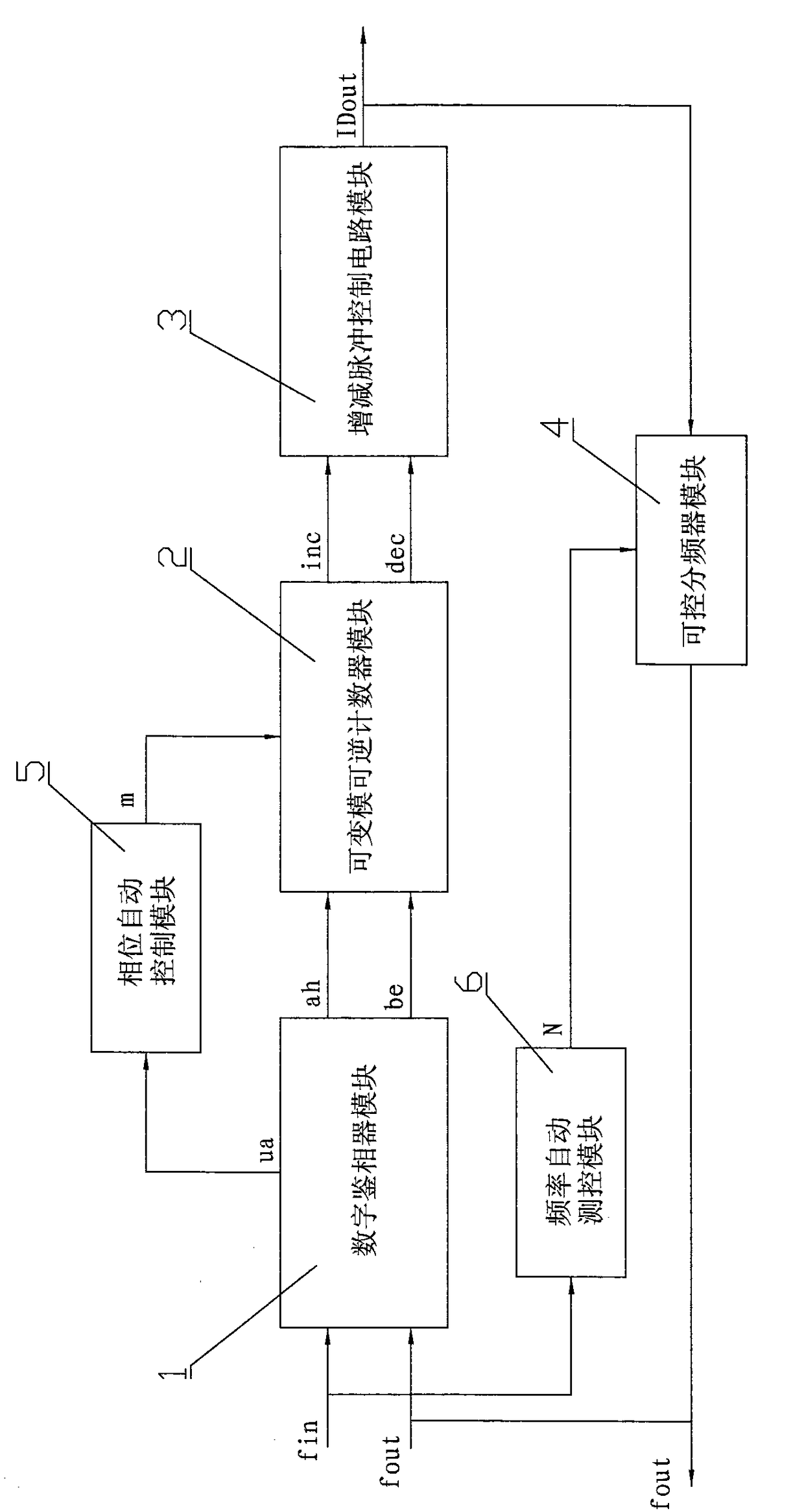
[0052] All-digital phase-locked loop in frequency conversion domain, including digital phase detection module 1, variable mode reversible counter module 2, increase and decrease pulse control circuit module 3, controllable frequency divider module 4, phase automatic measurement and control module 5 and frequency automatic measurement and control module 6 , using electronic design automation technology to complete the design of each module circuit.

[0053] The digital phase detector module 1 has two signal input terminals and three signal output terminals. The two signal input terminals are respectively the fin signal input terminal and the fout signal input terminal. Ring the rising edge of the input signal fin and the output signal fout, judge its phase error and polarity, and generate the leading phase difference polarity signal ah, the lagging phase difference polarity signal be, and the phase difference and frequency difference signal ua reflecting the input and output sig...


PUM


Abstract

The invention provides a variable-frequency-domain all-digital phase-locked loop and a phase-locked control method. A ua signal output end of a digital phase discriminator module is connected with the input end of a phase automatic measuring and control module. An ah signal output end and a be signal output end are respectively connected with the first signal input end and the second signal input end of a variable-model reversible counter module. The m signal output end of the phase automatic measuring and control module is connected with the third signal input end of the variable-model reversible counter module. The inc signal output end and the dec signal output end of the variable-model reversible counter module are respectively connected with two signal input ends of an increase-and-decrease pulse control circuit module. The IDout signal output end of the increase-and-decrease pulse control circuit module is connected with the first signal input end of a controllable frequency divider module. The N signal output end of a frequency automatic measuring and control module is connected with the second input end of the controllable frequency divider module. The fout signal output end of the controllable frequency divider module is connected with the fout signal input end of the digital phase discriminator. Through dynamically adjusting and controlling the parameter of a phase-locked loop system, automatic tracking and quick locking are realized in a relatively wide input signal frequency range.

Description

technical field [0001] The invention belongs to the technical field of electronic information, and in particular relates to an all-digital phase-locked loop in the frequency conversion domain and a phase-locked control method applied to a system on chip (SOC). Background technique [0002] The all-digital phase-locked loop is widely used in the fields of communication, signal processing, modulation and demodulation, clock synchronization, frequency synthesis and automatic control, and has become an indispensable basic component in various electronic equipment. [0003] The existing all-digital phase-locked loop has the following defects: [0004] One is that the phase-locking range is narrow, the purpose is single, and the versatility is not strong. The existing all-digital phase-locked loop is designed by the designer based on a single fixed frequency domain in a certain application field. The frequency locking range of each phase-locked loop is relatively small. When the ...

Claims


Application Information

Patent Timeline
Patent Type & Authority Patents(China)
IPC IPC(8): H03L7/085H03L7/18
CPCH03L7/085H03L7/18
Inventor 单长虹李凤华陈忠泽赵宇红王丽君刘丹丹
Owner NANHUA UNIV
Learn More