

Lawn mower
A lawn mower and motor technology, applied in harvesters, agricultural machinery and implements, applications, etc., can solve the problems of inconsistent two-wheel drive speed, high machine noise, low transmission efficiency, etc., and achieve simple and convenient operation. The effect of working noise and improving transmission efficiency
- Summary
- Abstract
- Description
- Claims
- Application Information
AI Technical Summary
Problems solved by technology
Method used
Image

Examples
Embodiment 1
[0057] A driving device, the driving device is driven by an electric motor or an internal combustion engine, has a control mechanism and a driving mechanism, and has a main body and an operating rod;
[0058] The drive mechanism includes:
[0059] rollers supporting the main body;
[0060] a motor driving at least one roller;
[0061] The transmission clutch mechanism arranged between the motor and the roller;
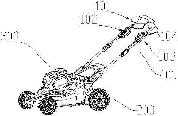
[0062] After the power output by the motor is distributed by the clutch, it is transmitted to the rollers through the reduction mechanism, and the rollers can rotate at different speeds. Such as figure 1 shown.
[0063] There is a control mechanism 100 on the operating rod, the driving wheel is controlled by the driving mechanism 200, and both the control mechanism 100 and the driving mechanism 200 are electrically connected to the control unit;
[0064]Wherein, the control unit is preferably a PCB control board.
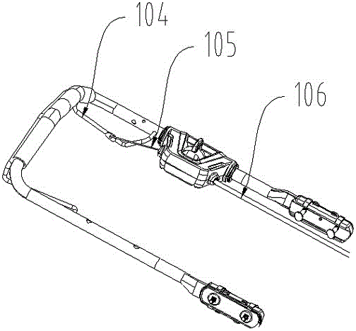
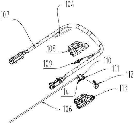
[0065] Such as figure 2 and image 3 As shown...
Embodiment 2
[0073] A lawnmower comprising
[0074] The mowing host includes a power component and a mowing component, and the power component drives the mowing component to run;
[0075] The operating rod for pushing, including the left push rod and the right push rod connected with the mowing host;
[0076] Walking wheels for walking, including front wheels and rear wheels located under the mowing main unit, such as figure 1 shown.
[0077] There is a control mechanism 100 on the operating rod, the driving wheel is controlled by the driving mechanism 200, and both the control mechanism 100 and the driving mechanism 200 are electrically connected to the control unit;
[0078] Wherein, the control unit is preferably a PCB control board.
[0079] Such as figure 2 and image 3 As shown, the control mechanism 100 includes a control mechanism one and a control mechanism two, and the control mechanism one includes a first operating member 104, a self-propelled cable 105, a self-propelled ...
PUM
 Abstract
Description
Claims
Application Information