Multifunctional manipulator

A multi-functional manipulator and arm technology, applied in the field of machinery, can solve the problems of damage to goods, simple structure of anti-loose mechanical gripper, low mechanical strength of mechanical gripper, etc., to prevent falling, high degree of automation and high mechanical strength Effect

Inactive Publication Date: 2016-09-28
XINXIANG UNIV
View PDF8 Cites 16 Cited by
  • Summary
  • Abstract
  • Description
  • Claims
  • Application Information

AI Technical Summary

Problems solved by technology

[0003] CN204172042U discloses a kind of anti-loosening mechanical gripper, comprises driving main shaft, driving sleeve, positioning shaft tube and two ratchets, and wherein driving main shaft is screw structure, and driving sleeve is screwed on driving main shaft, and positioning shaft tube It is located at the front end of the drive spindle, and the two sides of the drive sleeve are symmetrically provided with connecting arms. The other end of each connecting arm is pivotally connected to the rear of the ratchet. A return spring is arranged between the two ratchets. The two ratchets The front end of the front end forms a jaw, and the positioning shaft tube is clamped in the slot opened on the positioning plate on the two pawls. The positioning shaft tube can rotate in the slot, but the anti-loosening mechanical gripper has a simple structure. damage to the goods
[0004] CN203156750U discloses a multi-purpose mechanical gripper, comprising a mechanical arm, a rotating body is mounted on the front end of the mechanical arm, a gripper body is hinged on the rotating body, and a mechanism for driving the rotating body to rotate is installed on the mechanical arm. Rotating body hydraulic motor, a swing cylinder is hinged between the rotating body and the gripper body, the gripper body is provided with a connecting part, and the connecting part is connected with two sets of oppositely arranged mechanical fingers, the mechanical fingers A tension control device for controlling the gripping of the object by the mechanical fingers is connected, but the mechanical strength of the mechanical gripper is small

Method used


Image

  • Multifunctional manipulator
  • Multifunctional manipulator
  • Multifunctional manipulator

Examples


Embodiment Construction

[0020] Preferred embodiments of the present invention will be described in detail below in conjunction with the accompanying drawings.

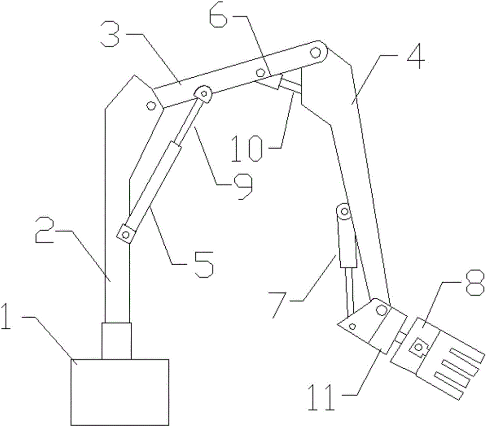
[0021] according to figure 1 As shown, a multifunctional manipulator includes a base 1, a column 2, a horizontal arm 3, a vertical arm 4, a lifting hydraulic cylinder 5, a swing hydraulic cylinder 6, a pitching hydraulic cylinder 7 and a gripper device 8, and the column 2 is welded to the base 1, the horizontal arm 3 is hinged to the column 2, the vertical arm 4 is hinged to the horizontal arm 3, the column 2 is provided with a lifting hydraulic cylinder 5, and the lifting hydraulic cylinder 5 is connected with the piston rod 9 The horizontal arm 3 is connected, and the vertical arm 4 is hinged on the horizontal arm 3. A swing hydraulic cylinder 6 is arranged at the end of the horizontal arm 3. The swing hydraulic cylinder 6 is connected to the vertical arm 4 through a swing rod 10. The vertical arm 4, a gripper device 8 is arranged below, a...


PUM


Abstract

The invention discloses a multifunctional manipulator. Rubber pads are arranged in a grasper and attached to the inner walls of the grasper, friction between the grasper and goods can be increased when the rubber pads get close to each other, and the goods can be prevented from being damaged by the grasper. Bolt holes are formed in the grasper, the rubber pads are fixed to the grasper through countersunk screws so that the rubber pads can be prevented from falling off. The rubber pads have the 10-degree inclination angle, labor can be saved during clamping and reliability is achieved. Pressure sensors are arranged on the inner walls of the grasper and can know grasping force of the grasper on the goods, and strength is prevented from being too large. Hydraulic cylinders are guide rod type spiral swinging hydraulic cylinders, the grasper can rotate by 360 degrees, objects are conveniently clamped, the number of lifting hydraulic oil cylinders is two, the number of swinging hydraulic oil cylinders is two, the number of pitching hydraulic oil cylinders is two, mechanical strength of the multifunctional manipulator can be improved, and the manipulator can work for a long time. The multifunctional manipulator has the advantages of being good in control effect, high in mechanical strength and high in automation degree, and has wide market prospects.

Description

technical field [0001] The invention relates to the mechanical field, in particular to a multifunctional manipulator. Background technique [0002] At present, the stacking of square objects at home and abroad is mainly done with forklifts. Due to the simple movement of the forklift and the limited stacking height, it cannot meet the stacking requirements of square objects in vehicles, ships and warehouses. Therefore, there is an urgent need for a multifunctional manipulator that can meet the requirements of fast stacking and loading and unloading of square objects. The invention is a multifunctional manipulator used for loading and unloading square objects, which can hold and carry objects according to a fixed program to complete certain specific operations. The multifunctional manipulator can replace people in monotonous repetitive or heavy physical labor, realize mechanization and automation of production, and replace people's manual operations in harmful environments. ...

Claims


Application Information

Patent Timeline
Patent Type & Authority Applications(China)
IPC IPC(8): B25J9/14
CPCB25J9/14
Inventor 杨棉绒张鑫
Owner XINXIANG UNIV
Why Eureka
Try Eureka