
Sanding roller core for fabric sanding machine and machining method

A processing method and the technology of the sanding machine, which are applied in the direction of fabric surface trimming, textile and papermaking, roughening, etc., can solve the problems of poor uniformity of the inner wall of the tube, slow startup, high energy consumption, and achieve small rotational inertia, excellent balance performance, The effect of high speed

Active Publication Date: 2016-09-28
SHANDONG GUANGTAI ENVIRONMENTAL TECH CO LTD
View PDF4 Cites 1 Cited by
  • Summary
  • Abstract
  • Description
  • Claims
  • Application Information

AI Technical Summary

Problems solved by technology

The defects of this kind of pipe are: 1, heavy weight, slow start, high energy consumption when rotating at high speed; 2, due to the poor uniformity of the inner wall of the seamless pipe, and it is difficult to level, so the overall dynamic balance and static balance of the sanding roller Both are checked, because the seamless pipe itself has poor straightness, poor surface finish, and uneven thickness, it is prone to radial runout when running at high speed; The pipe wall of the seamless pipe transmits power to the other side, so the thickness of the pipe wall cannot be reduced; 4. The current speed of the sanding roller is generally 800-1400 rpm, which is relatively high, but with the development of equipment Requirements, the speed is also expected to be increased to more than 2000 rpm

Method used


Image

  • Sanding roller core for fabric sanding machine and machining method
  • Sanding roller core for fabric sanding machine and machining method
  • Sanding roller core for fabric sanding machine and machining method

Examples


Embodiment Construction

[0038] The principles and features of the present invention are described below in conjunction with the accompanying drawings, and the examples given are only used to explain the present invention, and are not intended to limit the scope of the present invention.

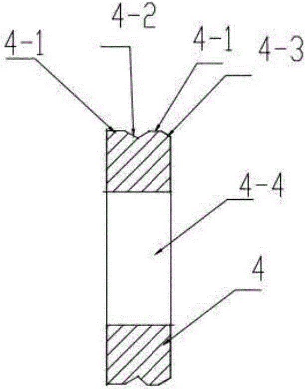
[0039] Such as Figure 1 to Figure 4 As shown, a sanding roller core for a fabric sanding machine includes a roller body 3, the roller body 3 is provided with a through shaft 1, and a plurality of supporting flanges are fixed on the through shaft 1 4. The outer edge of the supporting flange 4 is in interference fit with the inner hole of the roller body 3 .

[0040] Both ends of the roller body 3 are also fixedly provided with a shaft sleeve 2, and the outer edge of the shaft sleeve 2 is in interference fit with the inner hole of the roller body 3;

[0041] Such as figure 2 As shown, the outer edge of the shaft sleeve 2 is provided with at least one annular groove 4-2, which divides the outer edge of the shaft sl...


PUM


Abstract

The invention relates to a fabric sanding machine, in particular to a sanding roller core for the fabric sanding machine. The sanding roller core is characterized in that a roller body is included, a through shaft is arranged in the roller body, multiple support flanges are fixedly installed on the through shaft in a penetrating mode, and the outer edges of the support flanges are in interference fit with an inner hole of the roller body. The two ends of the roller body are fixedly provided with shaft sleeves, and the outer edges of the shaft sleeves are in interference fit with the inner hole of the roller body. The outer edges of the shaft sleeves and the outer edges of the support flanges are each provided with at least one annular groove, and the annular grooves divide the outer edge of the corresponding shaft sleeve into at least two convex annular surfaces. The invention further discloses a method. The method comprises the steps that 1, the through shaft, the support flanges and the shaft sleeves are prepared; 2, the support flanges and the shaft sleeves are fixed to the through shaft to form a support assembly; 3, the support assembly is pressed into the roller body along the axis; 4, balance is corrected. The sanding roller core has the advantages that the weight is small; the rotating inertia generated during rotating is small, and energy consumption is low; the dynamic and static balance properties are better.

Description

technical field [0001] The invention relates to a fabric sanding machine, in particular to a sanding roller core and a processing method for the fabric sanding machine. Background technique [0002] Sanded fabric is a kind of fabric that passes through a sanding machine, and the sanding roller on the sanding machine rubs the cloth to form a variety that is only fluffed on the appearance. While retaining the original properties of the fabric, the surface of the fabric forms a short texture. The feeling of the fluff layer not only reduces the thermal conductivity of the sanded fabric, but also increases the warmth retention and softness; the sanding roller is a key component for sanding the fabric, and a sanding machine generally uses 6 to 10 sanding rollers. wool roller. Therefore, its quality directly determines the sanding effect of the sanding machine. [0003] Generally, the diameter of the sanding roller is 100-130 mm, and the length is 2-2.5 meters. The speed of the s...

Claims


Application Information

Patent Timeline
Patent Type & Authority Applications(China)
IPC IPC(8): D06C11/00
CPCD06C11/00
Inventor 高景松
Owner SHANDONG GUANGTAI ENVIRONMENTAL TECH CO LTD
Learn More