Construction method for plain concrete underground diaphragm wall of deep foundation pit

A technology of underground diaphragm wall and construction method, which is applied in basic structure engineering, sheet pile wall, building and other directions, can solve the problem of high verticality requirements of I-beam joints in underwater precise construction grooves, increased construction period and cost, and inability to guarantee Water stop effect and other issues, to reduce the risk of joint leakage, reduce the construction period, and reduce the amount of chiseling

Active Publication Date: 2016-09-28
中铁十八局集团第五工程有限公司
View PDF5 Cites 5 Cited by
  • Summary
  • Abstract
  • Description
  • Claims
  • Application Information

AI Technical Summary

Problems solved by technology

The effective length of plain concrete is from the bottom of the wall to the bottom of the large foundation pit. However, due to the fact that the existing trough-forming equipment cannot meet the requirements of accurate underwater construction, and the verticality of the I-beam at the joint of the trough section is high, it is often adopted. The plain concrete underground diaphragm wall is poured to the ground, and when the foundation pit is excavated, it is excavated and removed to the bottom of the large foundation pit, which not only wastes materials, but a

Method used


Image

  • Construction method for plain concrete underground diaphragm wall of deep foundation pit
  • Construction method for plain concrete underground diaphragm wall of deep foundation pit
  • Construction method for plain concrete underground diaphragm wall of deep foundation pit

Examples


Example Embodiment

[0023] The technical solution of the present invention will be further described in detail below with reference to the accompanying drawings and specific embodiments. The specific embodiments described are only for explaining the present invention and are not intended to limit the present invention.
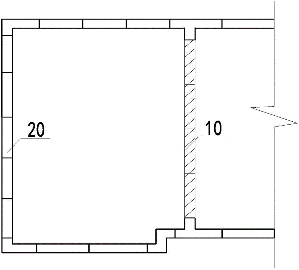
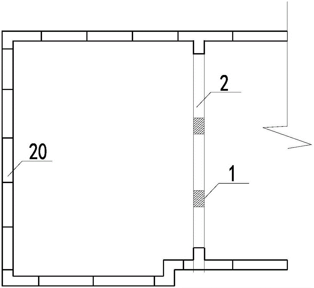
[0024] Normally, plain concrete underground continuous wall is to excavate a long and narrow deep groove on the ground with a groove forming machine. After forming a unit groove section, place a steel cage in the unit groove section, and then pour concrete to complete a unit wall section. , The unit wall sections are connected to each other in the form of I-steel, which is used for the hydraulic connection of diving and confined water inside and outside the retaining and partition pit.

[0025] The present invention proposes a method for constructing plain concrete underground continuous walls of deep foundation pits, in which the original plain concrete underground continuous walls 10...


PUM


Abstract

The invention discloses a construction method for a plain concrete underground diaphragm wall of a deep foundation pit. The construction method comprises the following steps: (1) conducting framing adjustment on a designed plain concrete underground diaphragm wall into a first slotted section and a closed slot section which are arranged at an interval, wherein the width of the first slotted section equals to the maximum width of the working part of a slotting machine; (2) carrying out construction of the first slotted section, then lowering reinforcement cages, pouring concrete to a level being 2 meters higher than the bottom surface of a basement floor, and then pouring the mortar of which the label is M10 to the ground level; and (3) carrying out construction of the closed slot section, then pouring concrete to a level being 2 meters higher than the bottom surface of the basement floor, and backfilling plain soil to the ground level, so as to form an underground diaphragm wall. The construction method disclosed by the invention has the advantages that as the reinforcement cages are improved, the original underground diaphragm wall smooth slotting method is replaced by spaced slotting method, and the number of the reinforcement cages abutting, concrete consumption, and the chiseling off workload in follow-up project are reduced; the operation is simple; safety risks and construction costs can be reduced; and construction time can be shortened.

Description

technical field [0001] The invention relates to a construction method of a plain concrete underground diaphragm wall of a deep foundation pit, specifically a reasonable, safe and reliable construction method of a plain concrete diaphragm diaphragm wall of a deep foundation pit, and belongs to the field of building deep foundation pit engineering. This method is applicable to the construction of similar engineering plain concrete underground diaphragm walls. Background technique [0002] With the continuous development of my country's infrastructure construction, the number of underground rail transit and high-rise buildings is increasing, and the excavation depth of foundation pits is increasing, and the impact of pressurized water on the safety of foundation pits is also increasing. As an effective foundation pit support method, the underground diaphragm wall has the characteristics of high rigidity and good impermeability. [0003] In the shield shafts of subway stations ...

Claims


Application Information

Patent Timeline
IPC IPC(8): E02D5/18
CPCE02D5/18
Inventor 谭伟姿郑卫红韩明建陈晓忠李海峰鄢伟苏天斌
Owner 中铁十八局集团第五工程有限公司
Why Eureka
Try Eureka