Drying machine steam chamber structure capable of adjusting steam feeding and steam shutting regionally

A steam chamber structure and dryer technology, applied in dryers, drying, heating devices, etc., can solve the problems of low heat exchange efficiency of dryers, and achieve the effects of simple structure, reduced consumption, and improved heat exchange efficiency

Inactive Publication Date: 2016-09-28
CITIC HEAVY INDUSTRIES CO LTD
View PDF5 Cites 4 Cited by
  • Summary
  • Abstract
  • Description
  • Claims
  • Application Information

AI Technical Summary

Problems solved by technology

[0004] In order to overcome the shortcomings of the existing dryer steam chamber structure pointed out in the background technology, the present invention provides a dryer steam chamber structure that can greatly improve the heat exchange efficiency of the steam rotary dryer, which can be adjusted into closed steam in different regions. Simple, strong operability, can effectively solve the problem of low heat exchange efficiency of the dryer

Method used


Image

  • Drying machine steam chamber structure capable of adjusting steam feeding and steam shutting regionally
  • Drying machine steam chamber structure capable of adjusting steam feeding and steam shutting regionally

Examples


Embodiment Construction

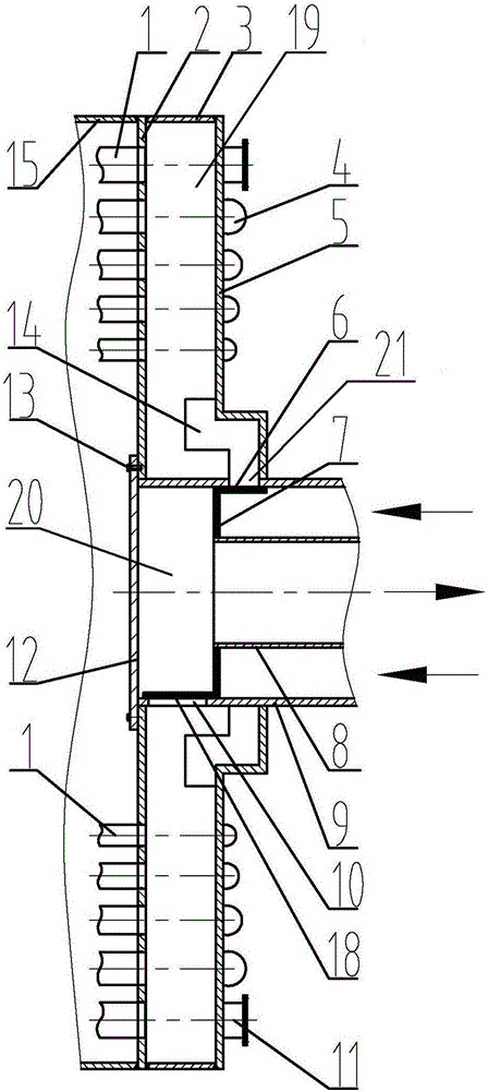
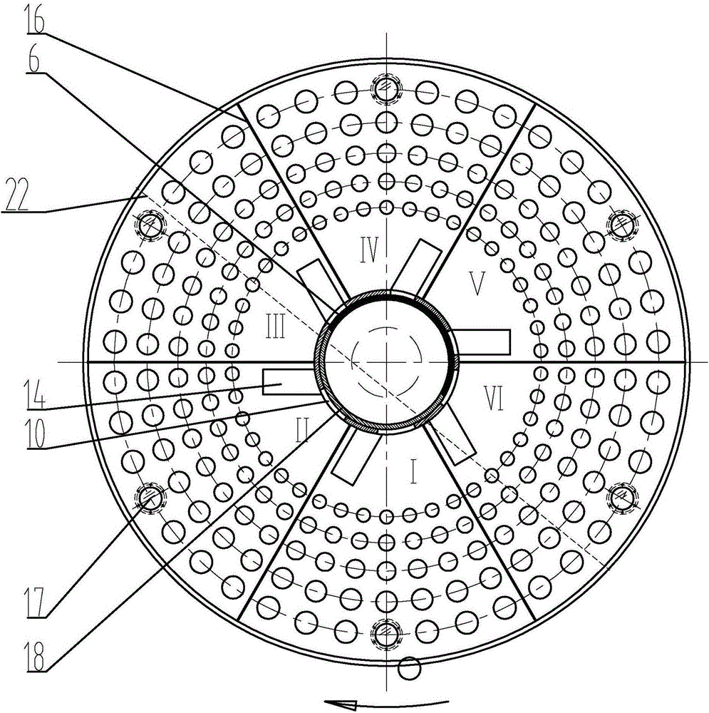
[0013] As shown in the figure, a dryer steam chamber structure that can be adjusted to enter and close steam in different regions includes a steam inlet pipe 9 with one end closed, and a closed cavity 19 is provided outside the steam inlet pipe 9 along its circumference to form a cavity. The wall plate of body 19 includes tube plate 2, end plate 5, steam chamber ring plate 3, and a section of tube wall at the closed end of steam inlet pipe 9. Tube plate 2 is circular, and its inner hole is connected with the outer wall of steam inlet pipe 9. , the baffle plate 12 at the closed end of the steam inlet pipe 9 is connected to the tube plate 2 by screws 13 so as to facilitate the replacement and maintenance of the steam blocking semi-ring plate 6 and the water vapor separator 7, the end plate 5 is annular and connected to the tube plate 2 Relatively arranged, the inner hole of the end plate 5 is connected with the outer wall of the steam inlet pipe 9, and the ring plate 3 of the ste...


PUM


Abstract

The invention relates to a steam chamber structure of a steam rotary type drying machine, in particular to a drying machine steam chamber structure capable of adjusting steam feeding and steam shutting regionally. The drying machine steam chamber structure comprises a closed cavity with heat exchange pipes, fan-shaped chambers formed by dividing the cavity through steam chamber division plates communicate with a steam supply channel through respective steam inlets and communicate with a drainage device through respective water outlet holes, a steam-blocking semi-ring plate is arranged inside the steam supply channel, and a water-blocking semi-ring plate is arranged inside the drainage device. In the rotation process of a cylinder body of the drying machine, the steam inlets of the fan-shaped chambers where the heat exchange pipes located above a material surface are located are blocked by the steam-blocking semi-ring plate, the water outlet holes of the fan-shaped chambers where the heat exchange pipes located above the material surface are located are not blocked, the water outlet holes of the fan-shaped chambers where the heat exchange pipes located below the material surface are located are blocked by the water-blocking semi-ring plate, and the steam inlets of the fan-shaped chambers where the heat exchange pipes located below the material surface are located are not blocked. According to the steam chamber structure, the function of feeding steam to the chambers corresponding to the heat exchange pipes in the material coverage area inside the cylinder body of the drying machine and stopping feeding steam to the other chambers is realized, the heat exchange efficiency of the drying machine is greatly improved, and the utilization efficiency of the heat energy of the high-temperature steam is greatly improved.

Description

technical field [0001] The invention relates to a steam chamber structure of a steam rotary dryer, in particular to a dryer steam chamber structure which can be adjusted into and closed by regions. Background technique [0002] As known, the steam rotary dryer is a rotary kiln equipment widely used in the chemical industry, coking and metallurgical industries. The material enters the cylinder of the steam rotary dryer through the screw feeding conveyor, and the high-temperature steam passes into the heat exchange tube, which indirectly heats and dries the material in the cylinder through the heat exchange tube. At the same time, due to the inclination and slow rotation of the dryer cylinder, the material continuously rolls and falls with the ball rotary kiln cylinder inside the cylinder, and advances from the kiln tail end (high end) to the kiln head end (low end) to remove Part of the moisture in the material is finally discharged from the kiln head of the dryer to complet...

Claims


Application Information

Patent Timeline
Patent Type & Authority Applications(China)
IPC IPC(8): F26B23/10
CPCF26B23/10
Inventor 刘星安崔郎郎王文煜乔斌朱世峰王凯王继光马艳梅冯燕尤立王观民梁志理
Owner CITIC HEAVY INDUSTRIES CO LTD
Why Eureka
Try Eureka