
A magnetic core sintering furnace system and its operating method

A sintering furnace and magnetic core technology, applied in the field of machinery, can solve the problems of only washing to the surface of the magnetic core, the cleaning effect is not ideal, and the purchase cost is high, so as to reduce the investment of processing capital, shorten the sintering time, and improve the utilization rate Effect

Active Publication Date: 2017-12-15
HAINING HUAYUE ELECTRONICS CO LTD
View PDF4 Cites 0 Cited by
  • Summary
  • Abstract
  • Description
  • Claims
  • Application Information

AI Technical Summary

Problems solved by technology

Although these two methods can complete the cleaning of the magnetic core, if ultrasonic cleaning equipment is used, not only the purchase cost is high, but also regular maintenance of the equipment is required; if the magnetic core on the conveyor belt is washed directly with hot water, a On the one hand, it can only be washed to the surface of the magnetic core, and the cleaning effect is not ideal; on the other hand, the water needs to be heated, and the cost is also high

Method used


Image

  • A magnetic core sintering furnace system and its operating method
  • A magnetic core sintering furnace system and its operating method
  • A magnetic core sintering furnace system and its operating method

Examples


Embodiment Construction

[0033] The following are specific embodiments of the present invention and in conjunction with the accompanying drawings, the technical solutions of the present invention are further described, but the present invention is not limited to these embodiments.

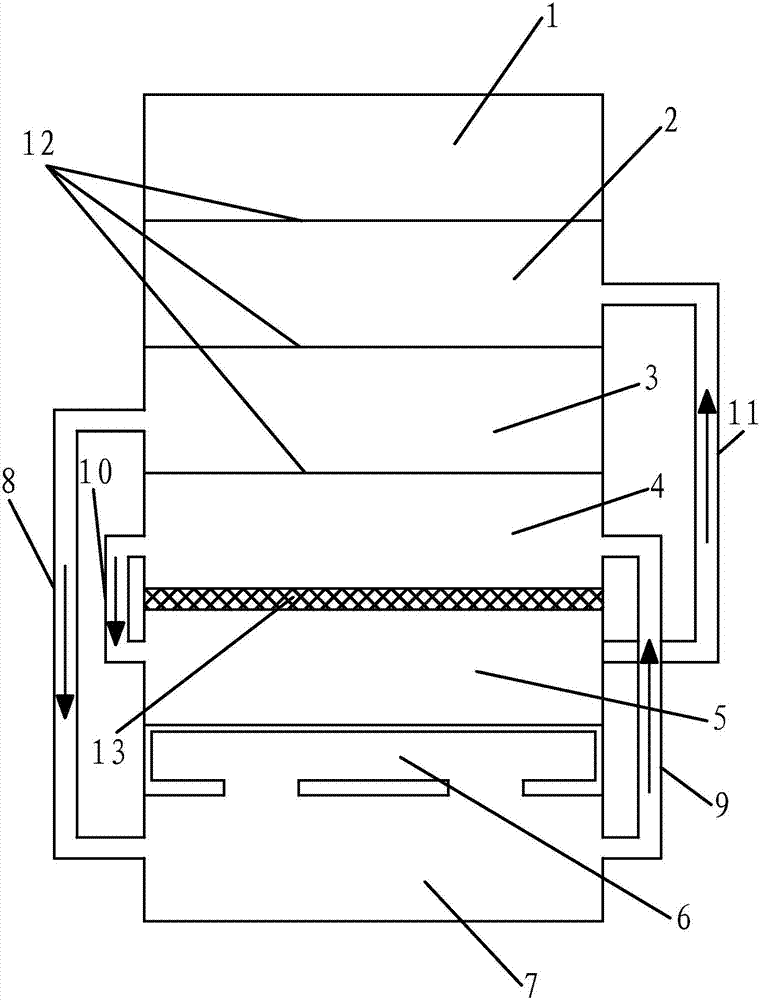
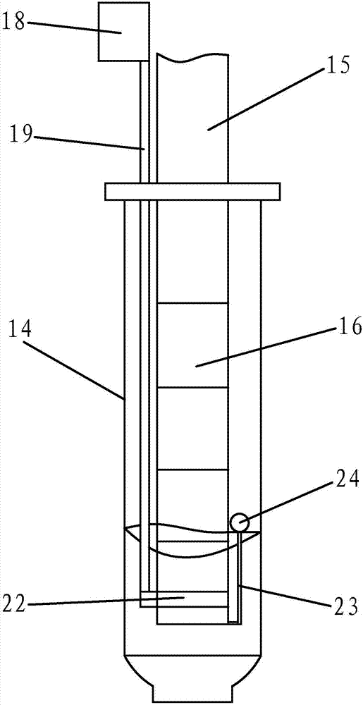
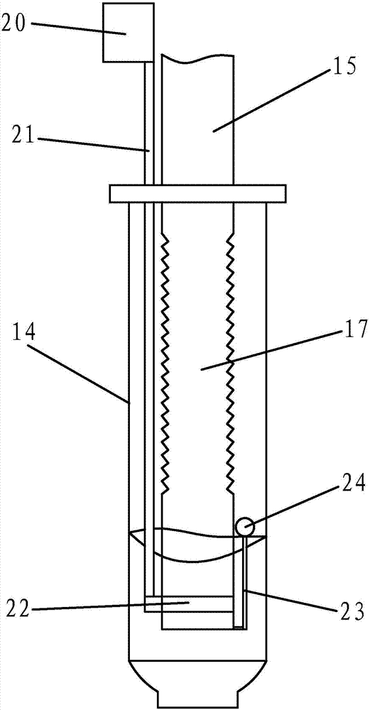
[0034] like Figure 1 to Figure 4 As shown, the magnetic core sintering furnace system includes a furnace body with a furnace cavity, which is characterized in that the furnace cavity is divided into a plurality of parallel independent reaction chambers from top to bottom, and these independent reaction chambers are sequentially from top to bottom Reaction chamber 2 in the heat dissipation area, reaction chamber 3 in the preheating area, reaction chamber 4 in the low temperature area, reaction chamber 5 in the high temperature area, and reaction chamber 7 in the adhesive discharge area; The reaction chamber 3 is connected to the reaction chamber 7 of the glue removal area through the first feeding pipe 8, the reaction cham...


PUM


Abstract

The invention provides a magnetic core sintering furnace system and an operating method thereof. This magnetic core sintering furnace system includes a furnace body with a furnace cavity. From top to bottom, the furnace cavity is composed of a heat dissipation zone reaction chamber, a preheating zone reaction chamber, a low temperature zone reaction chamber, a high temperature zone reaction chamber and a debinding zone reaction chamber; The reaction chamber in the preheating area is connected to the feed inlet. The reaction chamber in the preheating area is connected to the reaction chamber in the glue discharge area through the first feeding pipe. The reaction chamber in the glue discharge area is connected to the low temperature zone reaction chamber through the second feeding pipe. The low temperature zone reaction chamber passes through the third feeding pipe. The feeding pipe is connected to the high-temperature zone reaction chamber, the high-temperature zone reaction chamber is connected to the heat dissipation zone reaction chamber through the fourth feeding pipe, and the heat dissipation zone reaction chamber is connected to the discharge port; the heat dissipation zone reaction chamber is connected to the preheating zone reaction chamber, and the preheating zone reaction chamber is connected to the low temperature zone reaction chamber. The reaction chambers in the zone are separated by heat exchange plates. The reaction chambers in the low-temperature zone and the reaction chambers in the high-temperature zone are separated by heat-insulating plates. A thermal insulation interlayer is set between the reaction chamber in the high-temperature zone and the reaction chamber in the debinding zone. The thermal insulation interlayer passes through heat transfer The pipeline is connected to the reaction chamber of the glue discharge area.

Description

technical field [0001] The invention belongs to the technical field of machinery, and relates to a sintering device, in particular to a magnetic core sintering furnace system and an operation method thereof. Background technique [0002] The sintering furnace is a kind of high temperature, which makes the solid particles of the ceramic green body bond with each other, the grains grow, the voids (pores) and grain boundaries gradually decrease, and the total volume shrinks and the density increases through the transfer of substances. A furnace that becomes a dense polycrystalline sintered body with a certain microstructure. The sintering furnace is mainly used for sintering of ceramic powder, ceramic ferrule and other zirconia ceramics, sintering of diamond saw blades, and can also be used for heat treatment such as annealing of copper and steel strips. [0003] In the production process of the magnetic core, it is necessary to put the pressed and cut magnetic core into a tun...

Claims


Application Information

Patent Timeline
Patent Type & Authority Patents(China)
IPC IPC(8): F27B17/00F27D17/00B08B1/02F26B21/00B08B1/20
CPCF26B21/003F27B17/00F27D17/004B08B1/20Y02P10/25
Inventor 陈利明周浙锋王建良夏建忠
Owner HAINING HUAYUE ELECTRONICS CO LTD
Learn More