
A kind of gravity heat pipe device and preparation method

A gravity heat pipe and adiabatic section technology, applied in the field of heat pipes, can solve problems such as weakening condensation heat transfer performance, and achieve the effects of improving liquid film evaporation capacity, good infiltration effect, and heat transfer capacity.

Inactive Publication Date: 2018-01-30
SHANGHAI JIAO TONG UNIV
View PDF7 Cites 0 Cited by
  • Summary
  • Abstract
  • Description
  • Claims
  • Application Information

AI Technical Summary

Problems solved by technology

In the condenser of the ordinary heat pipe, film condensation occurs. This condensate film adheres to the wall of the evaporator, and the additional liquid film thermal resistance generated weakens the condensation heat transfer performance.

Method used


Image

  • A kind of gravity heat pipe device and preparation method
  • A kind of gravity heat pipe device and preparation method
  • A kind of gravity heat pipe device and preparation method

Examples


Embodiment Construction

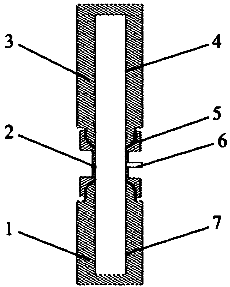
[0037] Such as figure 1 As shown, the gravity heat pipe device provided by the present invention with a super-hydrophilic evaporator and a SLIPS condenser includes: an evaporator 1 , an adiabatic section 2 , a condenser 3 and a working fluid filling port 6 . The evaporator 1 has a superhydrophilic surface 7 and the condenser 3 has a SLIPS surface 4 . The evaporator 1 and the heat insulation section 2 and the condenser 3 and the heat insulation section 2 are connected by a threaded tapered sealing surface 5 , and the working fluid filling port 6 is arranged on the side of the heat insulation section 2 . The inner diameters and lengths of the evaporator 1, the adiabatic section 2 and the condenser 3 are variable and can be adjusted according to actual conditions. The evaporator 1 and the condenser 3 only need to be able to reach super-hydrophilic and SLIPS surfaces respectively. Among them, the superhydrophilic surface is a surface with a contact angle of less than 5°, and the...


PUM


Abstract

The invention discloses a gravity assisted heat pipe device which comprises an evaporator, a heat insulation segment and a condenser. The evaporator and the condenser are in sealed connection with the heat insulation segment. The inner surface of the evaporator is a super-hydrophilic surface. The inner surface of the condenser is a smooth lubricant implanted porous surface (SLIPS). Lubricant on the SLIPS and a charged working medium cannot be mixed. A super-hydrophilic surface of a nano-micro structure is arranged on the inner wall of the evaporator, the working medium can completely moisten the wall face, a liquid film evaporates in the heating process, the evaporation intensity is improved, and the SLIPS of the condenser is formed by compounding the super-hydrophilic of a nano structure with implanted fluorine-containing lubricant or silicone oil or ionic liquid. Condensed liquid drops float on the SLIPS, are combined, fast fall off the SLIPS and sweep small liquid drops on the path of the condensed liquid drops, a condensation surface is provided for secondary condensation, and the condensation and heat exchange effect is remarkably improved. According to the gravity assisted heat pipe device, heat pipe heat resistance can be effectively reduced, the heat exchange performance of the device is improved, and wide application prospects are achieved.

Description

technical field [0001] The invention relates to the field of heat pipes, in particular to a gravity heat pipe device based on a bionic structure surface, which is used for waste heat recovery, cooling of electronic equipment, heat transport and the like. Background technique [0002] Heat pipes have been widely used in various industrial fields such as energy utilization and refrigeration. The heat pipe quickly absorbs the heat of the equipment through the evaporation of the evaporator to generate steam, and then releases the absorbed heat through the condensation process in the condenser, so as to achieve rapid heat transfer from the equipment. purpose of delivery. In the condenser of the ordinary heat pipe, film condensation occurs. This condensate film adheres to the wall of the evaporator, and the additional liquid film thermal resistance generated weakens the condensation heat transfer performance. Therefore, in order to reduce the influence of the additional liquid fi...

Claims


Application Information

Patent Timeline
Patent Type & Authority Patents(China)
IPC IPC(8): F28D15/02
CPCF28D15/02
Inventor 张鹏吕凤勇
Owner SHANGHAI JIAO TONG UNIV
Learn More