Multistatic radar multi-target imaging positioning method

A positioning method and multi-target technology, applied in the field of multi-static radar multi-target imaging positioning based on adaptive OMP, can solve the problems of difficulty in realization, side lobe crosstalk, affecting the quality of three-dimensional image space imaging, etc.

Active Publication Date: 2016-09-28
LESHAN NORMAL UNIV
View PDF4 Cites 15 Cited by
  • Summary
  • Abstract
  • Description
  • Claims
  • Application Information

AI Technical Summary

Problems solved by technology

The first one is that the output waveform after pulse compression of the linear frequency modulation signal is approximately a Sinc function (see "Pi Yiming, Yang Jianyu, Fu Yusheng, Yang Xiaobo. Principles of Synthetic Aperture Radar Imaging. First Edition. University of Electronic Science and Technology Press .2007.3"), there are main lobe broadening and side lobe crosstalk problems, which lead to a decrease in range resolution, which seriously affects the imaging quality in the three-dimensional image space and reduces the correctness and accuracy of the positioning method
The second shortcoming is that when this method extracts the target from the image space, the number of targets in the detection area needs to be known, and this condition is usually difficult to achieve in practical applications
However, the premise of the OMP algorithm is that the number of non-zero elements in the original sparse signal needs to be known (corresponding to multi-static radar multi-target imaging positioning, that is, the number of targets in the detection area needs to be known), if the original sparse signal is non-zero The number is unknown, and the reconstruction performance of the algorithm will be severely degraded

Method used


Image

  • Multistatic radar multi-target imaging positioning method
  • Multistatic radar multi-target imaging positioning method
  • Multistatic radar multi-target imaging positioning method

Examples


Embodiment 1

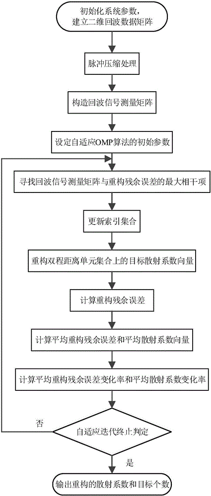
[0060] S1010. Initialize system parameters and establish a two-dimensional echo data matrix

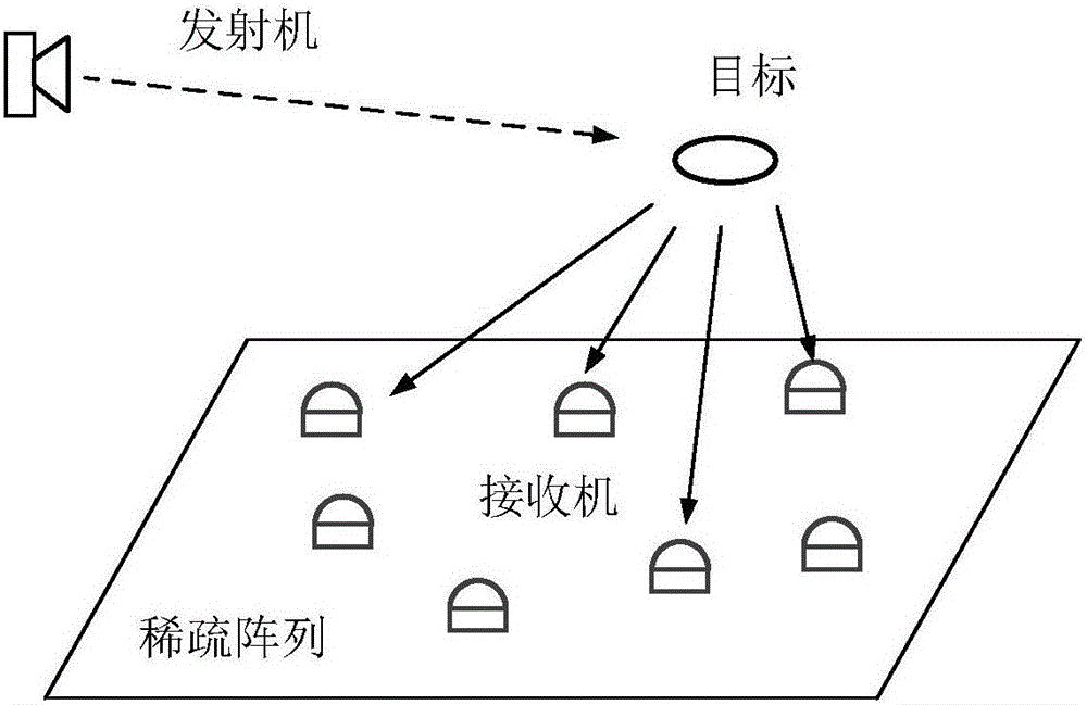
[0061] Prepare the transmitter and receiver, and initialize the system parameters: the system is composed of a transmitter and S receivers, where S=20; Establish the X-Y-Z Cartesian Cartesian coordinate system in the geographical space where it is located, and record the coordinate position of the transmitter as T=[0,0,0] T , and the coordinate position of the receiver is denoted as r j =[x j ,y j ,z j ] T , j=1,2,…,20, where receivers 1, 2, and 3 are respectively located at r 1 =[-25,0,0] T km, r 2 =[25,0,0] T km and r 3 =[0,43,0] T km, receivers 4-20 are randomly scattered in the triangular area determined by receivers 1, 2, and 3; the farthest detection distances of the system in the X direction, Y direction, and Z direction are XX max =50.5km, YY max = 50.5km and ZZ max = 10.5km, the closest detection distance is XX min =49.5km, YY min = 49.5km and ZZ min =9.5km; T...


PUM


Abstract

The invention relates to a multistatic radar multi-target imaging positioning method which comprises the steps of initializing system parameters, establishing a two-dimensional echo data matrix, conducting a pulse compression processing, constructing an echo signal measurement matrix, setting initial parameters of an adaptive OMP algorithm, finding the maximal coherent item of the echo signal measurement matrix and reconstruction residual errors, updating an index set, reconstructing target scattering coefficient vectors on a round-trip distance unit set, calculating the reconstruction residual errors, calculating the average reconstruction residual error and the average scattering coefficient vector, calculating the average reconstruction residual error changing rate and an average scattering coefficient changing rate, and determining adaptive iteration termination. The average reconstruction residual error changing rate and the average scattering coefficient changing rate are used as determination conditions for determining iteration termination of an adaptive OMP algorithm, and the target number of a detection area is estimated by using the iteration termination frequency of the adaptive OMP algorithm. The multistatic radar multi-target imaging positioning method is applicable to multistatic radar multi-target imaging positioning in actual situation when the target number is unknown.

Description

technical field [0001] The invention belongs to the technical field of multistatic radar, and more specifically relates to an adaptive OMP-based multistatic radar multi-target imaging positioning method. Background technique [0002] In multistatic radar multi-target positioning, in order to achieve reliable positioning of multiple targets, data association needs to be completed first. However, complex data association algorithms restrict the real-time and accuracy of multistatic radar multi-target positioning. In order to solve the problem of data association, the multistatic radar multi-target imaging positioning method regards the multi-target positioning problem as a three-dimensional imaging problem, and projects the amplitude information of multiple receiver echo signals into the three-dimensional image space, and then extracts them one by one from the image space. Each goal, to achieve the positioning of multiple goals. The three-dimensional resolution of the image ...

Claims


Application Information

Patent Timeline
Patent Type & Authority Applications(China)
IPC IPC(8): G01S7/41G01S13/89G01S13/06
CPCG01S7/41G01S13/06G01S13/89
Inventor 樊玲
Owner LESHAN NORMAL UNIV
Why Eureka
Try Eureka