Unmanned aerial vehicle/motor control device and method

A technology of motor control and control information, applied in the field of motor control devices and unmanned aerial vehicles, can solve the problems of large space occupied by the motor control circuit printed circuit board, poor system stability, low communication efficiency, etc., to achieve control frequency and accuracy Does not slow down, improves speed and stability, reduces the effect of hardware size

Pending Publication Date: 2016-09-28
ZEROTECH (BEIJING) INTELLIGENCE TECH CO LTD
View PDF0 Cites 34 Cited by
  • Summary
  • Abstract
  • Description
  • Claims
  • Application Information

AI Technical Summary

Problems solved by technology

[0004] The object of the present invention is to provide an unmanned aerial vehicle, a motor control device and a method to solve the problems of large space occupied by the motor control circuit, complex wiring of the printed circuit board (PCB), poor system stability, and problems of the main control unit and the main control unit. Technical issues such as low efficiency of communication between execution units

Method used


Image

  • Unmanned aerial vehicle/motor control device and method
  • Unmanned aerial vehicle/motor control device and method
  • Unmanned aerial vehicle/motor control device and method

Examples


no. 1 example

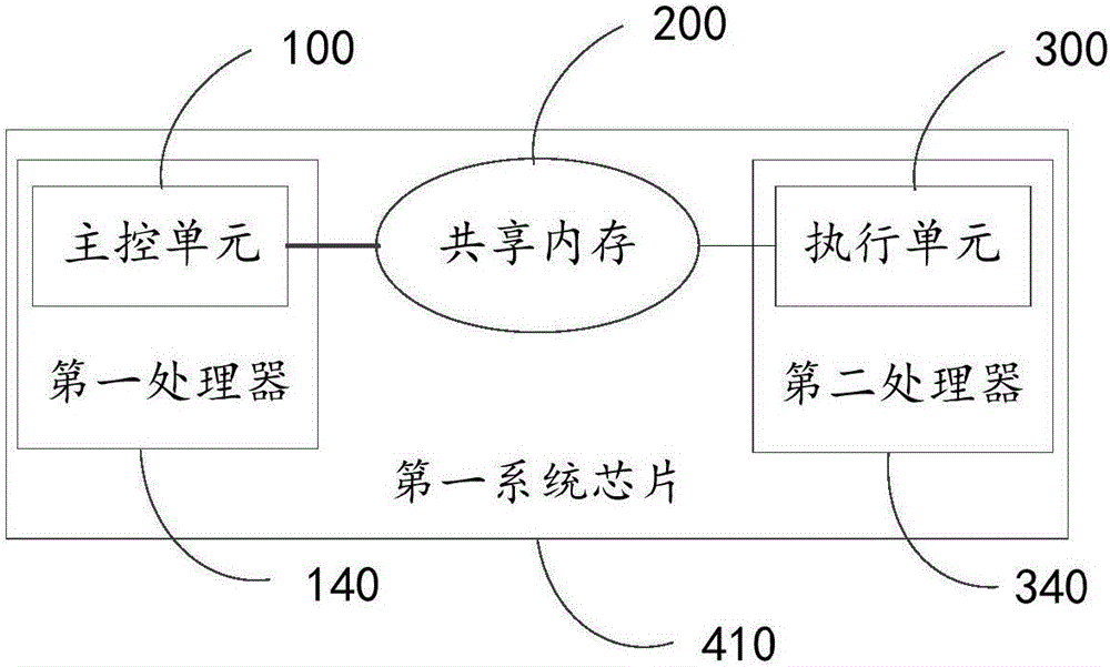
[0024] figure 2 A structural block diagram of the motor control device provided by the embodiment of the present invention is shown, and the motor control device provided by the embodiment of the present invention is used to adjust the load to a target attitude by controlling one or more motors on the load. The motor control device provided in the embodiment of the present invention includes: a main control unit 100 , a shared memory 200 and an execution unit 300 , the main control unit 100 is set in the first processor 140 , and the execution unit 300 is set in the second processor 340 , and the first processor 140 , the shared memory 200 and the second processor 340 may be integrated on the first system chip 410 . Data interaction between the main control unit 100 and the execution unit 300 is realized through the shared memory 200 .

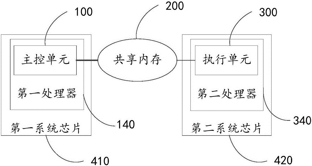
[0025] Such as image 3 As shown, in another embodiment, the first processor 140 may be disposed on the first system chip 410 , and the se...

no. 2 example

[0048] Figure 7 A flow chart of the motor control method provided by the embodiment of the present invention is shown. The motor control method provided by the embodiment of the present invention includes the following steps:

[0049] In step S1, the current operating parameter information of one or more motors on the load is obtained and stored in the shared memory.

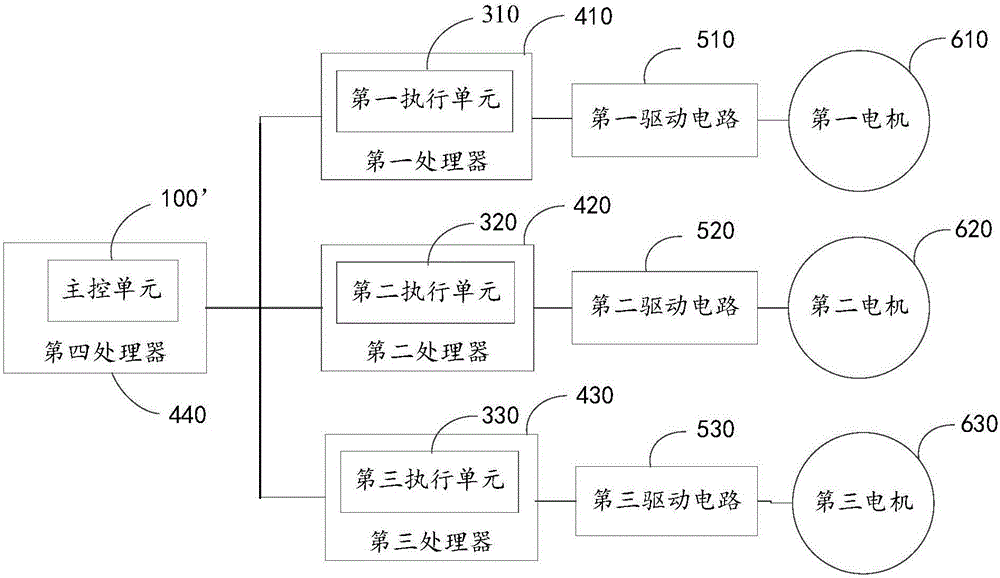
[0050] In the embodiment of the present invention, step S1 may be implemented by the execution unit 300 . The current operating parameter information of the motor includes: the power of the motor, the frequency of the motor, the voltage and current of the motor, and the current angle data of the motor, etc., wherein the current angle data of the motor may include the electrical angle of the rotor of the motor. The first motor 610, the second motor 620, and the third motor 630 are all equipped with magnetic encoders, which can obtain the electrical angle of the motor rotor at any time, and then, the execution ...


PUM


Abstract

The embodiments of the invention provide an unmanned aerial vehicle / motor control device and method. The motor control method comprises the following steps: acquiring current attitude information of the load, target attitude information of the load and current operation parameter information of one or more motors on the load, and obtaining control information for controlling the one or more motors according to the current attitude information, the target attitude information and the current operation parameter information; transmitting the control information to a shared memory for storage; and reading the control information from the shared memory and controlling the operation of one or more motors according to the control information. A motor control device according to the invention does not need connection of cables or PCB wiring, thereby reducing hardware size; the motor control device is directly implemented inside a chip through a shared memory, thereby improving the speed and stability of data interaction between a main control unit and an executing unit. Further, a correlation algorithm is adopted for ensuring the no reduction of motor and pan-tilt control frequency and accuracy.

Description

technical field [0001] The invention relates to the technical field of unmanned aerial vehicle flight control, in particular, to an unmanned aerial vehicle, a motor control device and a method. Background technique [0002] The gimbal can be coupled with the drone to carry cameras, lights, etc. The pan-tilt is equipped with a motor, and the high-speed attitude of the pan-tilt is realized by the motor, which receives the signal from the controller to run and position accurately. The controller of the motor includes a main control unit and an execution unit. The main control unit is used for the processing of sensor data, as well as functions such as gimbal stabilization and follow-up during the flight of the UAV. The execution unit is used to control the rotation of the motor according to the relevant data of the main control unit. [0003] Such as figure 1 As shown, the solution of the related art is to calculate in real time the motors on the three axes (the first motor...

Claims


Application Information

Patent Timeline
Patent Type & Authority Applications(China)
IPC IPC(8): H02P29/00H02P5/00H02P21/22G05D1/08
CPCG05D1/0808H02P5/00H02P29/00B64D47/08B64C39/024B64U2101/30H02P5/56G05D1/0094
Inventor 孙宇詹先龙朱晓陈一峰杨建军
Owner ZEROTECH (BEIJING) INTELLIGENCE TECH CO LTD
Why Eureka
Try Eureka