
A malodorous gas purification treatment system and treatment method thereof

A malodorous gas and purification treatment technology, which is applied in chemical instruments and methods, separation methods, and separation of dispersed particles, can solve the problems of purification module failure, equipment purification effect decline, and space occupation, and achieve high purification efficiency.

Active Publication Date: 2018-10-30
JIANGSU LANG YI ENVIRONMENTAL TECH CO LTD
View PDF6 Cites 0 Cited by
  • Summary
  • Abstract
  • Description
  • Claims
  • Application Information

AI Technical Summary

Problems solved by technology

This malodorous gas purification equipment usually has the following deficiencies: (1) Since the malodorous gas must be collected first and then purified, the traditional malodorous gas purification equipment is bulky and takes up a lot of space, making it difficult to move and use conveniently
(2) There is a problem that the purification effect is not good due to serious dust accumulation
This is because the malodorous gas carries a large amount of dust. If the air in the external environment is not introduced, the dust in the malodorous gas will adhere to various parts of the malodorous gas purification equipment, block the pipeline and make the purification module invalid, and then As a result, the purification effect of the entire equipment drops sharply, and eventually the malodorous gas purification equipment cannot be used normally in a short period of time.
In order to solve this problem, it is necessary to frequently replace the purification module and other related components, which increases the cost of manpower, material resources and financial resources

Method used


Image

  • A malodorous gas purification treatment system and treatment method thereof
  • A malodorous gas purification treatment system and treatment method thereof
  • A malodorous gas purification treatment system and treatment method thereof

Examples


Embodiment Construction

[0051] The advantages of the present invention will be further elaborated below in conjunction with the accompanying drawings and specific embodiments.

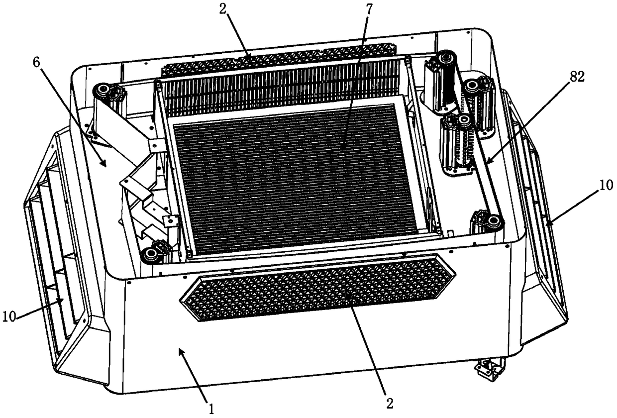
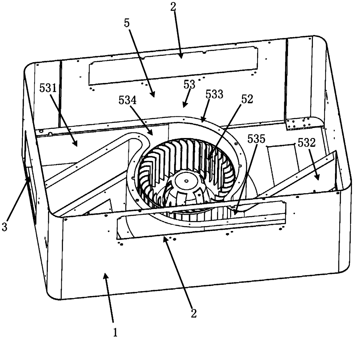
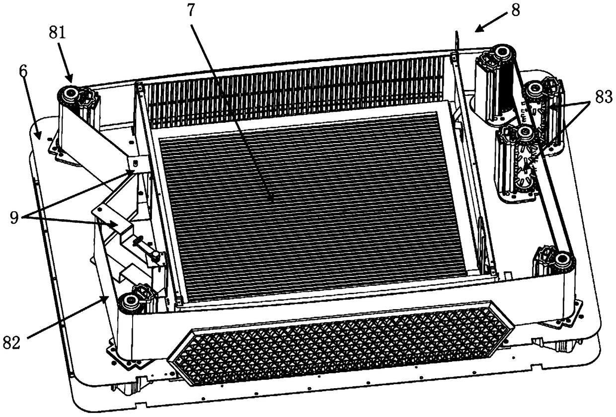
[0052] The malodorous gas purification treatment system according to the preferred embodiment of the present invention can be installed as an independent device in places where malodorous gas is generated, such as garbage collection stations, sewage treatment plants, breeding farms, and toilets. Such as figure 1 , figure 2 with Figure 7 As shown, the malodorous gas purification treatment system according to the preferred embodiment of the present invention at least includes: a housing 1 , an air inlet 2 , an exhaust port 3 , a purification module 4 , and an exhaust control device 5 .

[0053] First, combine figure 1 with figure 2 The casing 1 will be described. Such as figure 1 with figure 2 As shown, an air inlet 2 and an exhaust port 3 are formed on the housing 1, wherein the air inlet 2 is used to introduce the ...


PUM


Abstract

The invention provides a foul gas purifying treatment system which comprises a shell and a purifying module arranged in the shell. A gas inlet and an exhaust opening are formed in the shell. The purifying module is used for purifying foul gas and comprises a photocatalyst, and the photocatalyst and oxygen in the foul gas react to generate purifying particles. The foul gas purifying treatment system is further provided with an exhaust control device, the exhaust control device is used for introducing the foul gas into the shell from the gas inlet and exhausting the purified foul gas and the purifying particles out of the shell from the exhaust opening, the foul gas purifying treatment system controls the rate of the entering gas and the rate of the exhausted gas through the exhaust control device, and therefore the purifying effect is improved. The foul gas purifying treatment system is small in size, good in purifying effect and especially suitable for purifying the indoor foul gas. In addition, the invention provides a foul gas purifying treatment method.

Description

technical field [0001] The invention relates to a malodorous gas purification treatment system and a treatment method thereof. Background technique [0002] Residential garbage transfer stations, sewage treatment chiefs, breeding farms, toilets and other places usually produce a large amount of malodorous gas. The malodorous gas not only smells bad but also contains many harmful components, which has a negative impact on people's health and the surrounding environment. . Therefore, how to effectively deal with malodorous gas has become an urgent problem to be solved. [0003] At present, most of the traditional methods are still used in the treatment of malodorous gases in the prior art, mainly including: combustion method, activated carbon adsorption method, biological decomposition method, chemical spraying method, plasma method and so on. The above treatment methods are based on different deodorization principles to purify the malodorous gas. Although the odor pollution...

Claims


Application Information

Patent Timeline
Patent Type & Authority Patents(China)
IPC IPC(8): B01D53/86B01D46/00B01D46/22B01D46/10
Inventor 李庆生周德林李炯
Owner JIANGSU LANG YI ENVIRONMENTAL TECH CO LTD
Learn More