Cold-and-hot water unit with plate-pipe composite heat-exchange evaporative condenser

An evaporative condenser, cold and hot water unit technology, applied in the direction of evaporator/condenser, refrigerator, refrigeration components, etc. Installation and disassembly are cumbersome and other problems, to achieve the effect of increasing the evaporation area of ​​cooling water, reducing the volume of the condenser, and increasing the effective heat exchange area

Inactive Publication Date: 2016-10-05
GUANGZHOU WIDE IND
View PDF13 Cites 2 Cited by
  • Summary
  • Abstract
  • Description
  • Claims
  • Application Information

AI Technical Summary

Problems solved by technology

Multiple packing sheets are installed on the coil by buckles, etc., and the installation and disassembly are cumbersome; in this installation method, the packing sheets and the coil will not be tightly installed, which can meet the needs of guiding the spray water to form a water film. However, it cannot meet the needs of direct heat exchange with the coil, and the packing sheet is not a heat exchange material, so it cannot exchange heat with the coil
Therefore, although the invention patent has improved the heat exchange efficiency to a certain extent, the heat exchange efficiency has not been greatly improved because the heat exchange efficiency is only improved by increasing the utilization rate of cooling water.

Method used


Image

  • Cold-and-hot water unit with plate-pipe composite heat-exchange evaporative condenser
  • Cold-and-hot water unit with plate-pipe composite heat-exchange evaporative condenser
  • Cold-and-hot water unit with plate-pipe composite heat-exchange evaporative condenser

Examples


Embodiment 1

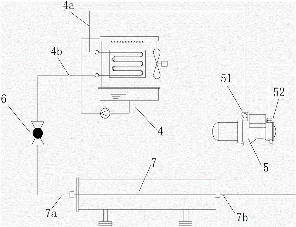
[0030] figure 1 It shows a schematic diagram of the principle of the refrigeration cycle mode of a cold and hot water unit with a plate-tube composite heat exchange type evaporative condenser according to the present invention. figure 1 It can be seen that the cold and hot water unit includes a compressor 5, an evaporative condenser 4, a throttling device 6 and an evaporator 7; the exhaust port 51 of the compressor 5 is connected with the gas pipe 4a of the evaporative condenser 4 to evaporate The liquid pipe 4b of the type condenser 4 is connected with the liquid pipe 7a of the evaporator 7 through the throttling device 6, and the gas pipe 7b of the evaporator 7 is connected with the suction port 52 of the compressor 5. The evaporative condenser 4 adopts plate-tube composite heat exchange fins, which will not be described in detail here.

[0031] Working principle: When the refrigerant is compressed by the compressor 5 and becomes a high-temperature and high-pressure gas, it...

Embodiment 2

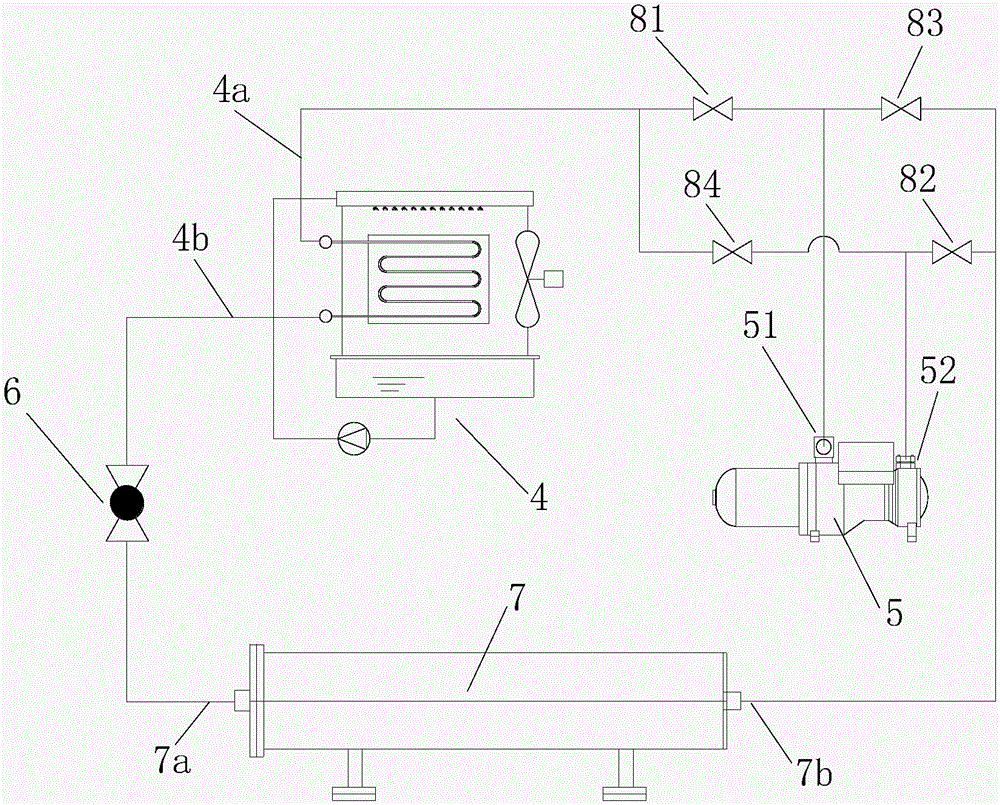
[0033] figure 2 It shows a schematic diagram of the principle of the cold and hot water unit of the present invention. Compared with Embodiment 1, the difference is that the cold and hot water unit is provided with a first refrigeration valve 81, a second refrigeration valve 82, a first heat pump Valve 83 and the second heat pump valve 84; the first refrigeration valve 81 is arranged on the connection pipeline between the exhaust port 51 of the compressor 5 and the gas pipe 4a of the evaporative condenser 4, and the second refrigeration valve 82 is arranged on the compressor 5 On the connecting pipeline between the suction port 52 of the compressor 5 and the gas pipe 7b of the evaporator 7, the first heat pump valve 83 is arranged on the connecting pipeline between the exhaust port 51 of the compressor 5 and the gas pipe 7b of the evaporator 7, and the second heat pump valve The pump valve 84 is arranged on the connection pipeline between the suction port 52 of the compressor...

Embodiment 3

[0036] Figure 4 It shows the schematic diagram of the principle of the two-position three-way reversing valve used in the hot and cold water unit of the present invention. Compared with Embodiment 1, the difference is that the exhaust port 51 of the compressor 5 is provided with a first two-position Three-way reversing valve 85, the suction port 52 of the compressor is provided with the second two-position three-way reversing valve 86; 4a is connected to the gas pipe 7b of the evaporator, and the two inlets of the second two-position three-way reversing valve 86 are respectively connected to the gas pipe 4a of the evaporative condenser and the gas pipe 7b of the evaporator. Similarly, the evaporative condenser has 4 plate-tube composite heat exchange fins.


PUM


Abstract

The invention discloses a cold-and-hot water unit with plate-pipe composite heat-exchange evaporative condenser. The cold-and-hot water unit comprises an air compressor, an evaporative condenser, a throttling device and an evaporator. The evaporative condenser comprises a fan, a water pump, a water distributor and a water collecting pond and further comprises a plate-pipe composite heat exchanger formed by connection of multiple plate-pipe composite heat-exchange sheets through a water inlet collection pipe and a water outlet collection pipe. The plate-pipe composite heat-exchange sheets comprise heat-transfer plate sheets and coil pipes formed by machining of heat-exchange pipes. The heat-transfer plate sheets are provided with placing grooves. The shapes of the placing grooves are matched with shapes of the coil pipes. The coil pipes are placed in the placing grooves. The gaps between the coil pipes and the placing grooves are filled with heat-conducting bonding layers. The cold-and-hot water unit with the plate-pipe composite heat-exchange evaporative condenser has following beneficial effects: the heat-conducting bonding layers enable the heat-transfer plate sheets to be in fully contact with the coil pipes such that the heat-exchange area is effectively enlarged; the heat-transfer plate sheets can drain cooling water to form a continuous waterflow surface; the evaporation superficial area of cooling water is enlarged; and heat transfer efficiency is increased while the size of the condenser is reduced.

Description

technical field [0001] The invention relates to the field of heat exchange equipment, in particular to a cold and hot water unit with plate-type and coil-type combined type-changing evaporative condensers. Background technique [0002] The evaporative condenser of the cold and hot water units on the market at this stage usually uses curved coils to form a heat exchanger, and the outer surface of the heat exchanger is cooled by spray water, and the circulating spray water is used to evaporate and take away heat. However, the outer surface of the heat exchange tubes of this type of coil heat exchanger is generally smooth, and the heat exchange efficiency is low. At the same time, the heat exchange surface area of ​​cooling water evaporation is small, and the distance between the coils needs to be enlarged to increase the heat exchange time between cooling water and air, resulting in a bulky heat exchanger. On the other hand, since there is no medium between the upper and lowe...

Claims


Application Information

Patent Timeline
Patent Type & Authority Applications(China)
IPC IPC(8): F25B29/00F25B39/04F25B41/04F25B41/06F25B41/20F25B41/30
CPCF25B13/00F28F1/22
Inventor 李志明谭栋张勇
Owner GUANGZHOU WIDE IND
Why Eureka
Try Eureka