Large-tonnage rotation movement hydraulic machine

A hydraulic press and large-tonnage technology, applied in the field of hydraulic presses, can solve problems such as complex structure of synchronous feeding roller table, difficulty in ensuring horizontal conveying of plates, and limitation of adjustment accuracy, so as to achieve flexible and light rotation, improve processing accuracy and production efficiency, and reduce friction force effect

Active Publication Date: 2016-10-12
ANHUI DONGHAI MACHINE MFG CO LTD
View PDF11 Cites 10 Cited by
  • Summary
  • Abstract
  • Description
  • Claims
  • Application Information

AI Technical Summary

Problems solved by technology

However, the structure of the synchronous feeding roller table in this application is relatively complicated. When the weight of the board is large, its adjustment accuracy is limited, and it is difficult to ensure the horizontal conveying of the board, which may still easily cause the deflection of the feeding roller table.

Method used


Image

  • Large-tonnage rotation movement hydraulic machine
  • Large-tonnage rotation movement hydraulic machine
  • Large-tonnage rotation movement hydraulic machine

Examples


Embodiment 1

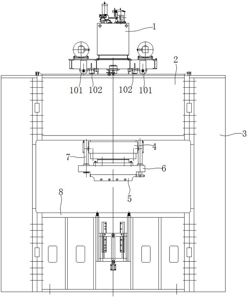
[0045] Such as figure 1 As shown, a large-tonnage rotary mobile hydraulic press of this embodiment includes a hydraulic press frame composed of an upper beam 2, a lower beam, and a column 3, a hydraulic station 1, a pressure head mechanism, and a workbench 8. The hydraulic station 1 is located at On the top of the hydraulic press frame, the pressure head mechanism is hoisted under the hydraulic station 1, and the upper beam 2 and the lower beam are processed into a rectangular box structure. Such as figure 1 As shown, the hydraulic station 1 of this embodiment is fixed on a traveling mechanism, which includes an upper trolley frame. The bottom of the upper trolley frame is provided with traveling rollers 101. The traveling rollers 101 drive the hydraulic station 1 along the rails of the upper beam 2 Move, the limit position on the left and right sides of the upper trolley frame is equipped with limit travel switches, and the bottom of the upper trolley frame is also provided wit...

Embodiment 2

[0055] A large-tonnage rotary mobile hydraulic press of this embodiment includes a hydraulic press frame composed of an upper beam 2, a lower beam and a column 3, a hydraulic station 1, a pressure head mechanism, and a workbench 8. The hydraulic station 1 is located on the hydraulic press frame At the top, the pressure head mechanism is hoisted under the hydraulic station 1, and the upper beam 2 and the lower beam are processed into a rectangular box structure. Such as figure 1 As shown, the hydraulic station 1 of this embodiment is fixed on a traveling mechanism, which includes an upper trolley frame. The bottom of the upper trolley frame is provided with traveling rollers 101. The traveling rollers 101 drive the hydraulic station 1 along the rails of the upper beam 2 Move, the limit position on the left and right sides of the upper trolley frame is equipped with limit travel switches, and the bottom of the upper trolley frame is also provided with upper trolley locking cylinde...


PUM


Abstract

The invention provides a large-tonnage rotation movement hydraulic machine, and belongs to the technical field of hydraulic machines. The large-tonnage rotation movement hydraulic machine comprises a hydraulic machine frame, a hydraulic station, a pressure head mechanism and a workbench, wherein the hydraulic machine frame comprises an upper beam, a lower beam and stand columns. The hydraulic station is located on the top of the hydraulic machine frame. The pressure head mechanism is hoisted below the hydraulic station. The workbench comprises a movement workbench and a rotation workbench, wherein the rotation workbench is located on an inner cavity of the movement workbench. Four travelling jack-up cylinders are symmetrically arranged below the movement workbench, three rotation jack-up cylinders which are evenly distributed are arranged below the rotation workbench in the circumferential direction of the rotation workbench, rolling wheels are arranged at the bottoms of the travelling jack-up cylinders, and rolling bearings are arranged between the rotation jack-up cylinders and the rotation workbench. The large-tonnage rotation movement hydraulic machine can be used for forming and machining large-tonnage plates, and the machining accuracy of the large-tonnage rotation movement hydraulic machine can be effectively guaranteed.

Description

Technical field [0001] The invention belongs to the technical field of hydraulic presses, and more specifically, relates to a large-tonnage rotary mobile hydraulic press. Background technique [0002] Hydraulic press is a device that uses hydraulic transmission technology for pressure processing, and can be used to complete various forging and press forming processing. At present, with the rapid development of my country’s shipbuilding industry, the demand for a large number of marine plates has also increased. CNC frame hydraulic press is one of the important processing equipment in the shipyard’s hull workshop. , Bending and forming of profiles and components. [0003] However, the workbenches of traditional hydraulic forming presses generally use workbenches that only have a moving function. When bending, the hydraulic press drives the mold to process the sheet workpiece, and the sheet workpiece is manually moved multiple times to complete the continuous bending in the width dir...

Claims


Application Information

Patent Timeline
Patent Type & Authority Applications(China)
IPC IPC(8): B30B1/32B30B15/00B30B15/30B30B15/34
CPCB30B1/32B30B15/0052B30B15/30B30B15/34
Inventor 陈宇石贤林石贤锋刘洋迟德益迟道根
Owner ANHUI DONGHAI MACHINE MFG CO LTD
Why Eureka
Try Eureka