
Portable cloth rolling machine for textile manufacturing machine

A kind of textile machinery and convenient technology, which is applied in the field of portable cloth winding machines for textile machinery, can solve the problems of lack of dehumidification device and dust absorption device, waste of precious time, complicated loading and unloading of long shaft, etc., and achieves high work efficiency and extended use. Longevity and guaranteed drying effect

Active Publication Date: 2016-10-12
抚顺恒跃工业用布有限公司
View PDF9 Cites 7 Cited by
  • Summary
  • Abstract
  • Description
  • Claims
  • Application Information

AI Technical Summary

Problems solved by technology

At present, the cloth rolling machines commonly used in the textile dyeing and dyeing industry are generally horizontal, consisting of a cloth supply device and a cloth rolling device arranged in front and back. The cloth rolling device rolls the cloth sent by the cloth supply device on a long axis Then supply it to the next process or store it in stock. The long axis of the cloth winding machine on this type of cloth winding machine is fixed with the cloth winding machine. After each cloth winding, the long axis needs to be disassembled. The long axis of the prior art The loading and unloading is complicated, a lot of precious time is wasted, the production cost is high, and the cloth often contains moisture. The cloth rolling machine in the prior art lacks a dehumidification device and a dust absorption device, which cannot meet the requirements of production and life.

Method used


Image

  • Portable cloth rolling machine for textile manufacturing machine
  • Portable cloth rolling machine for textile manufacturing machine
  • Portable cloth rolling machine for textile manufacturing machine

Examples


Embodiment Construction

[0018] The following will clearly and completely describe the technical solutions in the embodiments of the present invention with reference to the accompanying drawings in the embodiments of the present invention. Obviously, the described embodiments are only some, not all, embodiments of the present invention. Based on the embodiments of the present invention, all other embodiments obtained by persons of ordinary skill in the art without making creative efforts belong to the protection scope of the present invention.

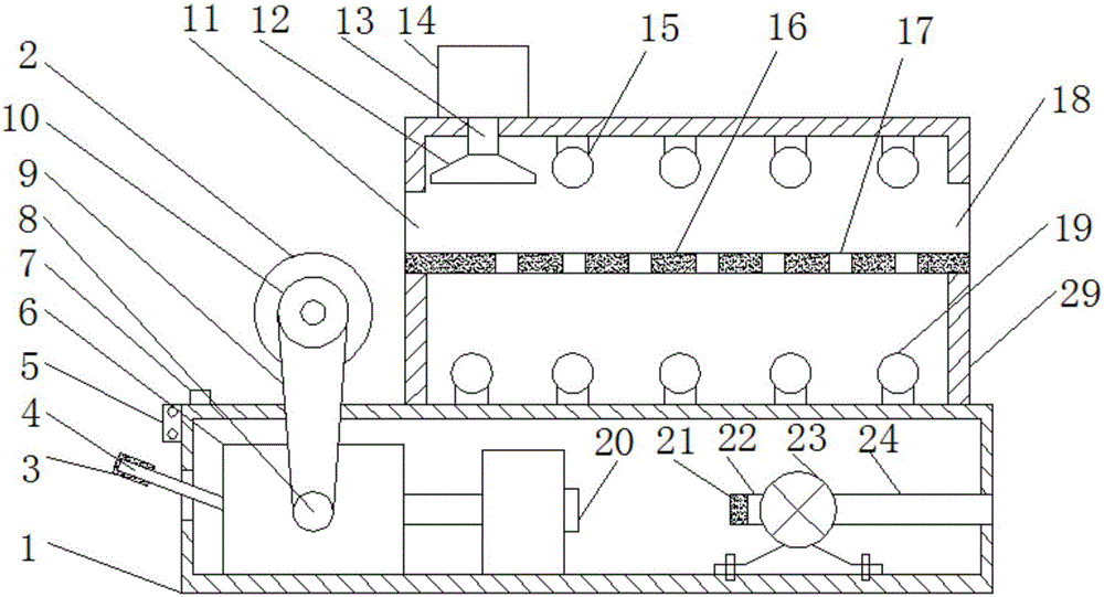
[0019] see Figure 1-5 , the present invention provides a technical solution: a portable fabric rolling machine for textile machinery, comprising a first housing 1 and a second housing 29, the top right side of the first housing 1 is fixedly connected with the second housing 29. The right side of the first casing 1 is fixedly connected with a fan 23, the left side of the fan 23 is connected with an air inlet pipe 22, and the air inlet pipe 22 is provided with ...


PUM


Abstract

The invention discloses a portable cloth rolling machine for a textile manufacturing machine. The portable cloth rolling machine comprises a first housing and a second housing. The second housing is fixedly connected to the right side of the top of the first housing. A fan is fixedly connected to the right side in the first housing. An air inlet pipe is connected with the left side of the fan. A filter screen is arranged in the air inlet pipe. An exhaust pipe is connected to the right side of the fan. A discharging opening is formed in the left side wall of the second housing. A feeding opening is formed in the right side wall of the second housing. A dust collector body is arranged at the left side of the top of the second housing. A dust collection pipe is connected with the bottom of the dust collector body. A dust collection hood is connected with the bottom of the dust collection pipe. A heat-conducting plate is arranged between the discharging opening and the feeding opening. Guiding plates are arranged on two sides of the heat-conducting plate. The upper surface of the heat-conducting plate and the top of a cloth roller are located at the same horizontal height. Heating lamps are arranged at the bottom of the second housing. The heating lamps, a rotary motor, the fan and a transmission are all connected with a controller electrically.

Description

technical field [0001] The invention relates to the technical field of textile machinery, in particular to a portable cloth winding machine for textile machinery. Background technique [0002] The working people of the Han nationality were able to produce silk fabrics as far back as 2700 BC. By the Han Dynasty, silk weaving production had reached a considerable scale, and a large number of exquisite silk fabrics were exported to Central Asia and Europe through the "Silk Road". In the Tang Dynasty, it was sold to Japan and Southeast Asia by sea. my country is a big producer and consumer of silk fabrics. [0003] In the textile production process, producers need to roll the cloth processed by the previous process into cloth rolls to facilitate the next process to continue processing. At present, the cloth rolling machines commonly used in the textile dyeing and dyeing industry are generally horizontal, consisting of a cloth supply device and a cloth rolling device arranged ...

Claims


Application Information

Patent Timeline
IPC IPC(8): B65H19/30B65H18/10B08B15/04A61L2/10F26B23/04
CPCB08B15/04B65H18/10B65H19/30F26B23/04
Inventor 姜丽
Owner 抚顺恒跃工业用布有限公司
Learn More