Building concrete pouring vibration robot

A technology of concrete and robots, which is applied in the fields of construction, building structure, and building materials processing, etc., can solve the problems of slow concrete filling, high labor intensity of operators, and accelerated damage speed, etc., to achieve slow solution speed and automation High, the effect of improving work efficiency

Active Publication Date: 2016-10-12
福建省东霖建设工程有限公司
View PDF6 Cites 8 Cited by
  • Summary
  • Abstract
  • Description
  • Claims
  • Application Information

AI Technical Summary

Problems solved by technology

[0004] In order to solve the above problems, the present invention provides a vibrating robot for building concrete pouring, which can solve the problems of slow concrete filling, high labor intensity of operators, and low work efficiency in the existing manual concrete pouring method, and can also solve the existing problems Concrete vibrating equipment has the problem of loose parts or accelerated damage due to long-term high-frequency vibration work. It can realize the function of multiple vibrating rods to enrich concrete pouring at the same time. With the help of parallel mechanism, it has good dynamic response, high rigidity, large bearing capacity, good stability and It has the advantages of high motion precision to reduce the vibration force when the vibrating equipment is working. It has the advantages of fast concrete filling, good vibration damping performance, high work efficiency and high degree of automation. It provides a new way to automate and quickly fill concrete

Method used


Image

  • Building concrete pouring vibration robot
  • Building concrete pouring vibration robot
  • Building concrete pouring vibration robot

Examples


Embodiment Construction

[0020] In order to make the technical means, creative features, goals and effects achieved by the present invention easy to understand, the present invention will be further described below in conjunction with specific illustrations.

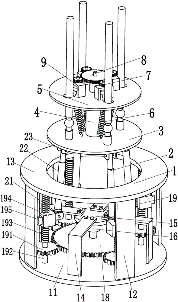
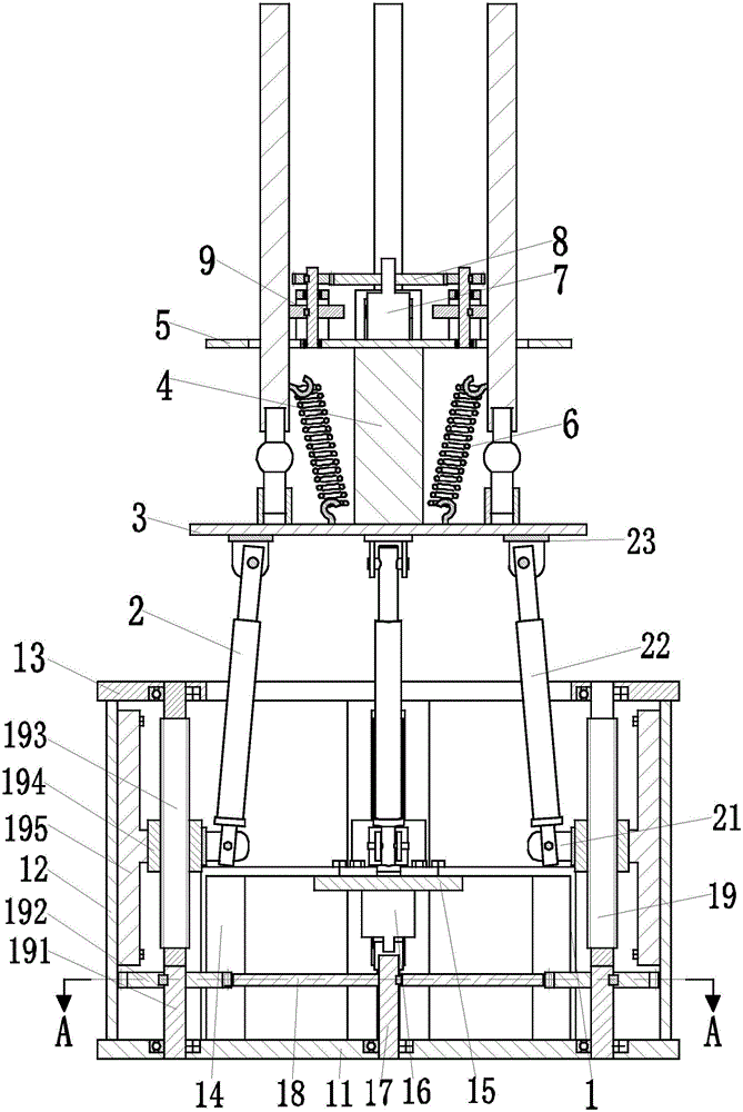
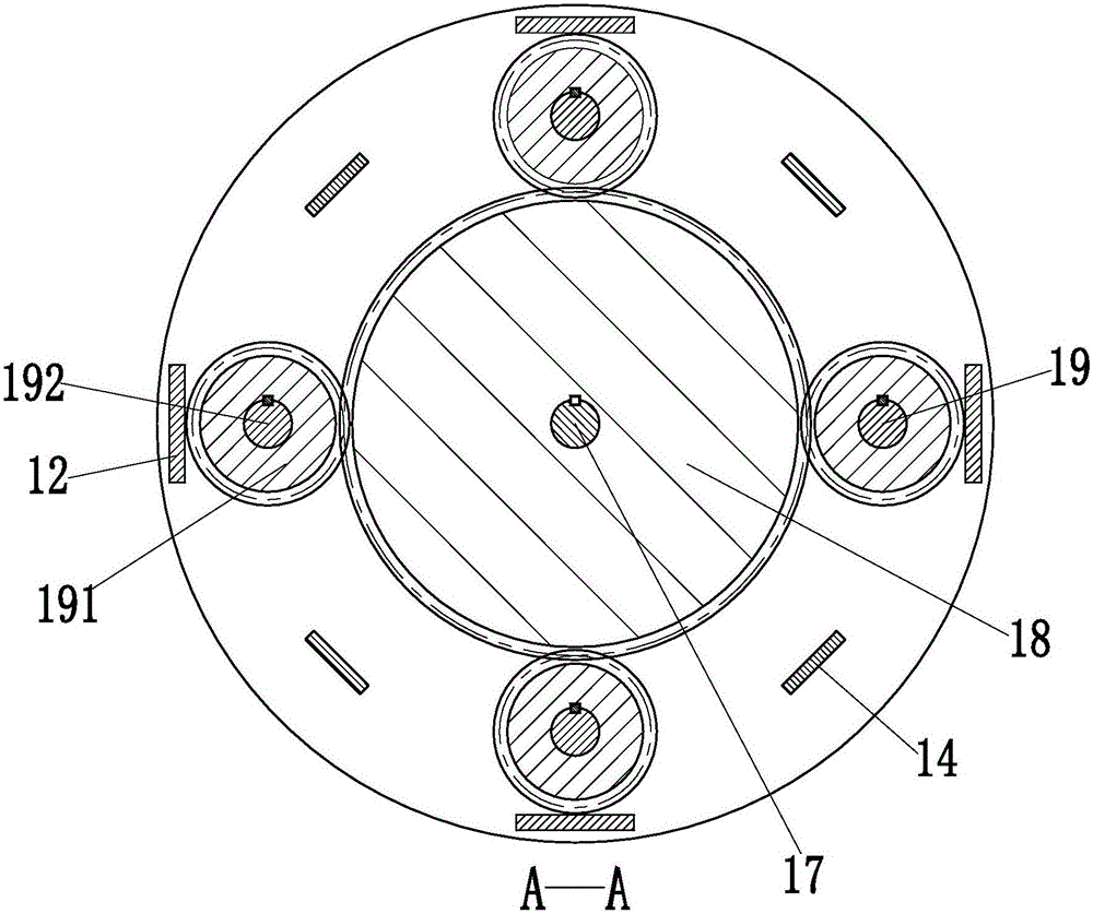
[0021] like Figure 1 to Figure 5 As shown, a building concrete pouring vibration robot includes a fixed frame 1, and the fixed frame 1 includes a fixed platform 11, and four support panels 12 are symmetrically welded on the outside of the upper end surface of the fixed platform 11, and the four support panels 12 The upper end is welded with an annular round table 13, and the support panel 12 plays the role of supporting the annular round table 13. The middle part of the annular round table 13 is provided with a circular opening; the upper end surface of the fixed table 11 is welded with four L-shaped supports 14 symmetrically inside. The upper end of each L-shaped support 14 is installed with mounting platform 15 by screw, and four L-shaped sup...


PUM


Abstract

The invention relates to a building concrete pouring vibration robot which comprises a fixing rack. Locating columns are arranged at the middle portion of the upper end face of an operation table. A limiting disc is welded to the upper ends of the locating columns. The locating columns achieve the effect of supporting the limiting disc. Four kidney-shaped limiting holes are evenly formed in the limiting disc in the axis direction. Four vibration branch chains are evenly installed on the operation table in the axis direction. The four vibration branch chains can conduct the high-frequency vibration movement on poured concrete at the same time, the concrete compacting speed is high, and the work efficiency is high. The middle portion of the upper end face of the limiting disc is provided with a transmission motor through a motor seat. A driving gear is fixedly installed at the output end of the transmission motor and engaged with four transmission branch chains. By the adoption of the robot, the function of compacting the poured concrete through multiple vibration bars at the same time can be achieved, the robot has the beneficial effects of being high in concrete compacting speed, good in damping performance, high in work efficiency, high in automation degree and the like, and a new way for automatically and quickly compacting the poured concrete is provided.

Description

technical field [0001] The invention relates to the technical field of building concrete, in particular to a vibrating robot for building concrete pouring. Background technique [0002] Concrete is a general term for engineering composite materials that use cementitious materials to cement aggregates into a whole. It is widely used in civil engineering. Concrete is one of the most important contemporary civil engineering materials. It is prepared in a certain proportion from cementitious materials, granular aggregates, water, and admixtures and admixtures added when necessary. After uniform mixing, it is densely formed and maintained. A hardened artificial stone. Concrete has the characteristics of abundant raw materials, low price, simple production process, high compressive strength, good durability, and wide range of strength grades. These characteristics make it widely used, not only in various civil engineering projects, but also in shipbuilding Concrete is also an im...

Claims


Application Information

Patent Timeline
Patent Type & Authority Applications(China)
IPC IPC(8): E01D21/00E04G21/08
CPCE01D21/00E04G21/08
Inventor 储茂松潘春燕
Owner 福建省东霖建设工程有限公司
Why Eureka
Try Eureka