Overlying strata abscission layer grouting technology and device

A technology of overlying strata separation and grouting, which is applied in the direction of safety devices, fillings, drilling equipment and methods, etc., can solve problems such as ecological environmental hazards, polluted land resources, and surface subsidence, so as to ensure compressive strength, High filling efficiency and good workability

Inactive Publication Date: 2016-10-12
HOHAI UNIV
View PDF6 Cites 7 Cited by
  • Summary
  • Abstract
  • Description
  • Claims
  • Application Information

AI Technical Summary

Problems solved by technology

However, my country's construction waste is basically disposed of in the open air or landfilled, which not only causes pollution and waste of land resources, but also brings great safety hazards
[0003] After the underground coal seam is mined, the original rock stress in the goaf and the overlying rock above the coal pillar is destroyed, causing the overlying rock to move, deform, fracture and even collapse, causing the surface to subside, causing damage to farmland and buildings. Serious harm to the ecological environment

Method used


Image

  • Overlying strata abscission layer grouting technology and device
  • Overlying strata abscission layer grouting technology and device
  • Overlying strata abscission layer grouting technology and device

Examples


Embodiment 1

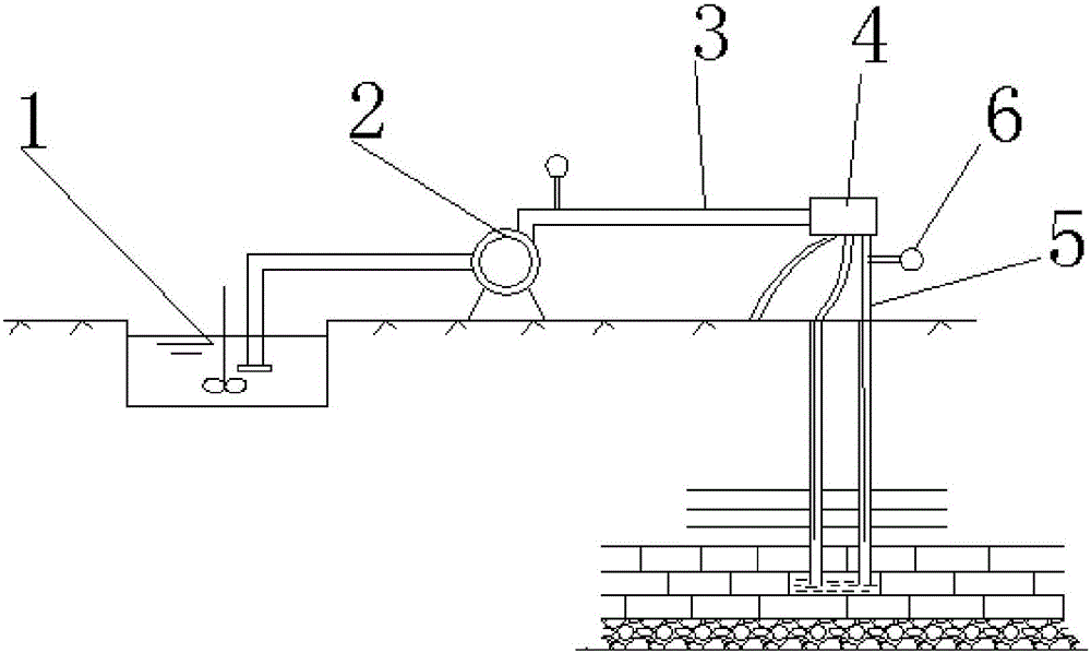
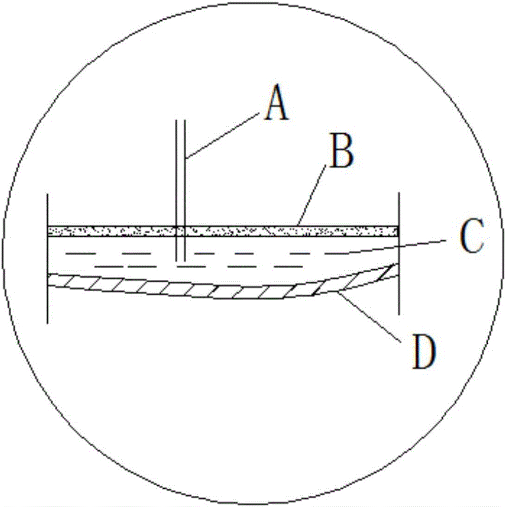
[0033] Such as figure 1 and figure 2 As shown, a grouting device for overburden separation layer includes a slurry pool 1, a pumping structure 2, a pipeline 3, a flow diversion device 4, a flow diversion pipeline 5 and a pressure gauge 6, wherein the inlet of the pumping structure 2 is connected to the slurry pool 1, and the outlet The diversion device 4 is connected through the pipeline 3, the outlet of the diversion device 4 is connected to the diversion pipeline 5, and a pressure gauge 6 is installed on each diversion pipeline 5 to monitor the pressure, and the diversion pipeline 5 extends into the borehole A, so that the slurry is injected into the separation layer space After being solidified into slurry C, it becomes a filling body with a certain strength. There is support between the upper rock layer B and the lower rock layer D, and the overlying rock is not easy to move, deform, break or even collapse.

[0034] An overlying rock separation layer grouting process, th...

Embodiment 2

[0047] A layer-separated grouting device for overlying rock, comprising a grout pool 1, a pumping structure 2, a pipeline 3, a diversion device 4, a diversion pipeline 5, and a pressure gauge 6, wherein the inlet of the pumping structure 2 is connected to the grout pool 1, and the outlet passes through the pipeline 3 Connect the diversion device 4, the outlet of the diversion device 4 is connected to the diversion pipe 5, and each diversion pipe 5 is equipped with a pressure gauge 6 to monitor the pressure, and the diversion pipe 5 extends into the borehole A, so that the slurry is injected into the separated layer space, and the slurry is solidified into a slurry After filling body C, it becomes a filling body with a certain strength. There is support between the upper rock layer B and the lower rock layer D, and the overlying rock is not easy to move, deform, break or even collapse. For the convenience of filling and better effect, the front section of the distribution pipeli...

Embodiment 3

[0061] A kind of overlying rock separation layer grouting process, different from embodiment 1: in step a, the distance between every two adjacent boreholes is 0.6m; in step b, the mass ratio of each component is 1:0.62:0.43: 0.16:0.005, the rest of the operation steps are the same.


PUM

PropertyMeasurementUnit
particle diameteraaaaaaaaaa

Abstract

The invention discloses an overlying strata abscission layer grouting technology and a device, and belongs to the technical field of mine filling. The overlying strata abscission layer grouting technology concretely comprises: a. drilling, specifically, estimating the size of an abscission layer space according to the survey result, and downwards drilling in fixed points of the surface of overlying strata; b. pulping, specifically, producing slurry coarse aggregate by taking construction wastes as raw materials, adding sand, coal ash, water and water reducing agent, stirring constantly and mixing to obtain grouting slurry; c. conveying, specifically, the grouting slurry flowing along a conveying pipeline under the pressurization effect of a pumping structure; and d. grouting, specifically, the slurry in the pipeline passing a shunt device to be shunted into multiple paths which flow to the abscission layer space, till the abscission layer space is filled up. According to the invention, the grouting slurry on the basis of construction wastes and in reasonable proportion is adopted, and multiple-path filling is realized, so that the effects of high filling efficiency, high strength, low cost, energy conservation and environmental protection are achieved.

Description

technical field [0001] The invention belongs to the technical field of mine filling, and in particular relates to a technique and a device for overlying rock separation layer grouting. Background technique [0002] With the acceleration of my country's urbanization process, the increasing development of new rural construction and the increasing number of old city renovation projects, a large amount of construction waste has been generated, such as waste concrete, waste bricks, waste blocks, etc. According to relevant data, the total amount of construction waste in my country accounts for about 30%-40% of the total amount of urban waste, and there is an increasing trend year by year. However, the treatment of construction waste in our country is basically open-air stacking or landfill, which not only causes pollution and waste of land resources, but also brings great safety hazards. [0003] After the underground coal seam is mined, the original rock stress in the goaf and t...

Claims


Application Information

Patent Timeline
Patent Type & Authority Applications(China)
IPC IPC(8): E21F15/00E21B7/00C04B28/00
CPCE21F15/005C04B28/00C04B2111/70E21B7/00
Inventor 张成辉石崇白金州沈俊良金成刘苏乐
Owner HOHAI UNIV
Why Eureka
Try Eureka