Fuel nozzle

A fuel injection nozzle and oil delivery technology, which is applied in fuel injection devices, special fuel injection devices, fuel injection devices with noise reduction measures, etc., can solve the problem of poor reliability of fuel injection nozzles, no flow, and affecting needle valves Opening and other problems to achieve the effect of improving noise and starting performance, improving cooling, and improving reliability

Active Publication Date: 2016-10-12
CHINA FAW LIMITED WUXI FUEL INJECTIONEQUIP RES INST +1
View PDF5 Cites 5 Cited by
  • Summary
  • Abstract
  • Description
  • Claims
  • Application Information

AI Technical Summary

Problems solved by technology

However, the fuel is sprayed from the needle valve head through the transverse hole and the longitudinal hole, and then from the fuel injection hole. The fuel between the transverse hole and the cylindrical sealing section in the oil delivery ring is not flowing, which often results in a small amount of fuel in a large amount. accumulation of particulate matter
The stagnant fuel is continuously heated by the high-temperature gas in the combustion chamber, and the temperature will continue to rise, resulting in chemical reaction decomposition and coking, which will affect the opening of the needle valve and lead to poor reliability of the fuel injector.

Method used


Image

  • Fuel nozzle
  • Fuel nozzle
  • Fuel nozzle

Examples


Embodiment 1

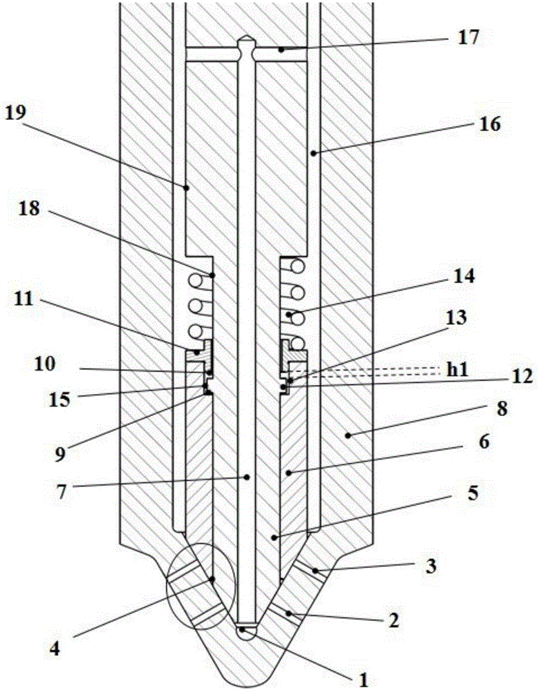
[0036] Such as figure 1 As shown, a fuel injection nozzle includes a needle valve, a needle valve body 8 coaxially arranged on the outer periphery of the needle valve, and an oil delivery channel arranged inside the needle valve body 8 .

[0037] The inside of the head of the needle valve body 8 is provided with a conical sealing surface, and two rows of spray holes are arranged alternately on the conical sealing surface, namely the upper row of nozzle holes 3 and the lower row of nozzle holes 2 .

[0038] The needle valve includes a first needle valve 5 with a variable cross-section cylindrical structure and a cylindrical second needle valve 6 . The first needle valve 5 and the second needle valve 6 are arranged coaxially, and both can move axially.

[0039] The first needle valve 5 includes a head cylinder 18 and a top cylinder 19 arranged above the head cylinder 18, and the diameter of the top cylinder 19 is greater than the diameter of the head cylinder 18; the middle par...

Embodiment 2

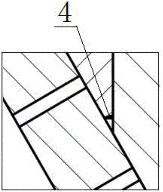
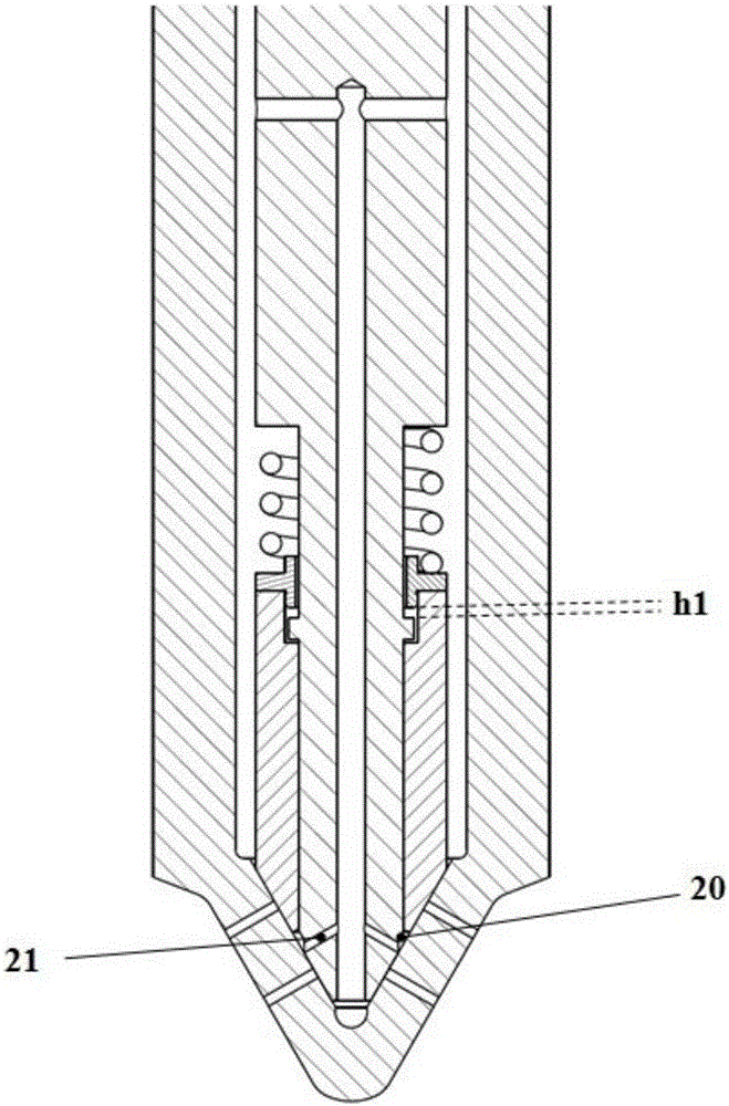
[0060] The structure and working principle of Embodiment 2 and Embodiment 1 are basically the same, and the only difference lies in the structural arrangement of the anti-seize mechanism. In embodiment 2, such as image 3 As shown, the anti-seize mechanism is the second annular groove 20 provided on the first sealing tapered surface of the head of the first needle valve 5 . The head of the first needle valve 5 is also provided with a plurality of side through holes 21 that can communicate the second annular groove 20 with the central shaft hole 7 . The diameter of the side through hole 21 is less than 1 / 2 of the diameter of the central shaft hole 7 .

[0061] The above-mentioned second annular groove 20 can prevent the guide surface between the first needle valve 5 and the second needle valve 6 from being stuck, and at the same time, it can also strengthen the fuel flushing of the area between the lower row of nozzle holes 2 and the upper row of nozzle holes 3 , to enhance c...


PUM


Abstract

The invention discloses a fuel nozzle. The fuel nozzle comprises a needle valve, a needle valve body and a fuel conveying passage; a conical sealing surface is arranged at the inner side of the head of the needle valve body; upper-row nozzle holes and lower-row nozzle holes are arranged in a staggered manner in the conical sealing surface; the needle valve comprises a first needle valve and a second needle valve which are arranged coaxially and are connected through a spring; the first needle valve is provided with an annular lug boss and is capable of sealing the low-row nozzle holes; the second needle valve extends into a first annular groove of the annular lug boss and is capable of sealing the upper-row nozzle holes. When the first needle valve is placed at the seat, an axial damping clearance is formed between the annular lug boss and the first annular groove. By adopting the structure, the first needle valve and the second needle valve can be used for respectively controlling fuel injection and implementing pre-injection, main injection and later injection. Meanwhile, cooling of the head of the fuel nozzle can be greatly improved. The axial damping clearance is capable of playing a buffering effect when the first needle valve is placed at the seat and effectively preventing rebound and reducing an impact force applied to the needle valve body when the needle valve is placed at the seat, so abnormal injection of a fuel injector can be prevented.

Description

technical field [0001] The invention relates to an internal combustion engine oil injection device, in particular to an oil injection nozzle. Background technique [0002] In compression-ignition internal combustion engines, pre-injection has been shown to improve engine noise and start-up performance, while injection after main injection reduces soot emissions. At present, in order to improve the economy and emission indicators of the internal combustion engine, higher requirements are put forward for the fuel injection system of the internal combustion engine. It is required that the post injection after the main injection requires a fast response time, and this includes common rail injectors. are difficult to achieve. Because the common rail injector realizes pre-injection, main injection, and post-injection through multiple injections, it can be known from the working principle of the common rail injector that the opening and closing of the needle valve is controlled by...

Claims


Application Information

Patent Timeline
Patent Type & Authority Applications(China)
IPC IPC(8): F02M61/12F02M61/18
CPCF02M61/12F02M61/1806F02M61/182F02M2200/06F02M2200/09F02M2200/185F02M2200/46
Inventor 郭立新宋永平周禛杨鹿缪雪龙杨海涛夏兴兰居钰生
Owner CHINA FAW LIMITED WUXI FUEL INJECTIONEQUIP RES INST
Why Eureka
Try Eureka