

Double-cylinder flow stabilizing delivery pump and trailer pump and pump truck adopting double-cylinder flow stabilizing delivery pump
A delivery pump and steady flow technology, which is applied to components, pumps, piston pumps, etc. of pumping devices used for elastic fluids, and can solve the impact of pumping equipment, delivery pipelines, valves, impacts on reliability and service life, and delivery Pipeline blockage and other problems, achieve the effect of stable delivery flow and pressure, not easy to fatigue damage, and eliminate pipe blockage
- Summary
- Abstract
- Description
- Claims
- Application Information
AI Technical Summary
Problems solved by technology
Method used
Image

Examples
Embodiment 1
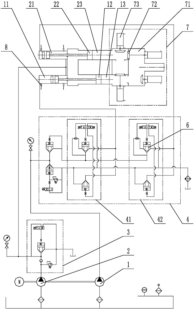
[0059] see figure 1 , which shows a schematic diagram of a dual-cylinder steady-flow delivery pump in a preferred embodiment of the present invention. The double-cylinder steady-flow conveying pump includes: pumping hydraulic pump 1, fast-reverse hydraulic pump 2, fast-reverse hydraulic valve group 3, pumping hydraulic valve group 4, cartridge valve 6, distribution valve group 7, pressure-resistant travel switch 8 , Pumping hydraulic cylinder A11, Pumping piston A12, Pumping cylinder A13, Pumping hydraulic cylinder B21, Pumping piston B22, Pumping cylinder B23, Pumping hydraulic valve group A41, Pumping hydraulic valve group B42, Distribution valve box 71, seat valve valve head 72, valve driving device 73.
[0060] In the figure, the part within the double-dot dash line indicated by serial number 3 is the fast-reverse hydraulic valve group, the part within the double-dot dash line indicated by serial number 4 is the pumping hydraulic valve group, and the part within the doubl...
Embodiment 2
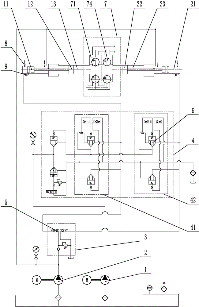
[0105] see figure 2 , which shows a schematic diagram of a double-cylinder steady-flow delivery pump according to another preferred embodiment of the present invention. The double-cylinder steady-flow conveying pump includes: pumping hydraulic pump 1, fast-reverse hydraulic pump 2, fast-reverse hydraulic valve group 3, pumping hydraulic valve group 4, hydraulic reversing valve 5, cartridge valve 6, distribution valve group 7 , pressure limit switch 8, one-way valve 9, pumping hydraulic cylinder A11, pumping piston A12, pumping cylinder A13, pumping hydraulic cylinder B21, pumping piston B22, pumping cylinder B23, pumping hydraulic valve group A41 , Pumping hydraulic valve group B42, distribution valve box 71, valve ball 74.
[0106] In the figure, the part within the double-dot dash line indicated by serial number 3 is the fast-reverse hydraulic valve group, the part within the double-dot dash line indicated by serial number 4 is the pumping hydraulic valve group, and the pa...
Embodiment 3
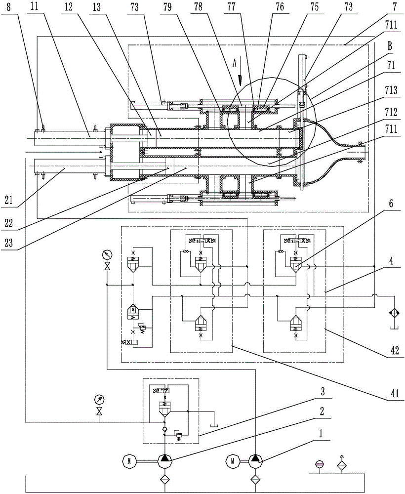
[0140] see image 3 , Figure 4 and Figure 5 , which shows a schematic diagram of a double-cylinder steady-flow delivery pump according to another preferred embodiment of the present invention. The double-cylinder steady-flow conveying pump includes: pumping hydraulic pump 1, fast-reverse hydraulic pump 2, fast-reverse hydraulic valve group 3, pumping hydraulic valve group 4, cartridge valve 6, distribution valve group 7, pressure-resistant travel switch 8 , Pumping hydraulic cylinder A11, Pumping piston A12, Pumping cylinder A13, Pumping hydraulic cylinder B21, Pumping piston B22, Pumping cylinder B23, Pumping hydraulic valve group A41, Pumping hydraulic valve group B42, Distribution valve box 71. Valve driving device 73, sliding body 75, sliding seal 76, elastic seal 77, guide rod 78, friction plate 79. The distribution valve box 71 further includes a distribution valve body 1 711 , a distribution valve body 2 712 and a distribution valve body 3 713 , and the distributio...
PUM
 Abstract
Description
Claims
Application Information