A Flow Field Uniform Device Based on Shrinkage Curve Design

A shrinking curve and curve technology, applied in the field of vibration and noise control of liquid-filled pipelines, can solve problems such as increased shaft frequency and blade frequency noise, poor effect, and distortion of the velocity field at the inlet of the flow channel.

Inactive Publication Date: 2019-03-19
NO 719 RES INST CHINA SHIPBUILDING IND
View PDF6 Cites 0 Cited by
  • Summary
  • Abstract
  • Description
  • Claims
  • Application Information

AI Technical Summary

Problems solved by technology

[0002] Generally speaking, the interior space of the engine room and other cabins of large ships is limited, and there is not enough space to arrange straight pipe sections for rectification at the pump inlet and valve outlet positions, and the excessively rapid system pipeline direction will directly affect the inflow status of water pumps and other equipment, resulting in Distortion occurs in the inlet velocity field of the flow channel at the inlet part of the impeller
According to the fluid inlet velocity triangle of the turbomachinery, too small or too large inlet velocity angle will cause the fluid to separate at the impeller blades. The shaft frequency and blade frequency noise of the pump are greatly increased
Long-term operation of the equipment in this imported state will reduce the service life of the equipment. In addition, the vibration of the equipment will increase and generate vibration noise, which will radiate noise outward through the system pipe network and the sea port, affecting the stealth performance of the ship.
At present, the rectification design for the inlet elbow of the pump and the flow field of the valve outlet is concentrated on the guide vane, but the guide vane has high requirements for processing and installation angle, and the effect is poor
At present, there has not been a flow field uniform device that can be applied in the field of fluid media such as water and oil, and can improve the flow field uniformity in a relatively short length range.

Method used


Image

  • A Flow Field Uniform Device Based on Shrinkage Curve Design
  • A Flow Field Uniform Device Based on Shrinkage Curve Design
  • A Flow Field Uniform Device Based on Shrinkage Curve Design

Examples


Embodiment Construction

[0019] The present invention will be further described below in conjunction with the accompanying drawings and specific embodiments.

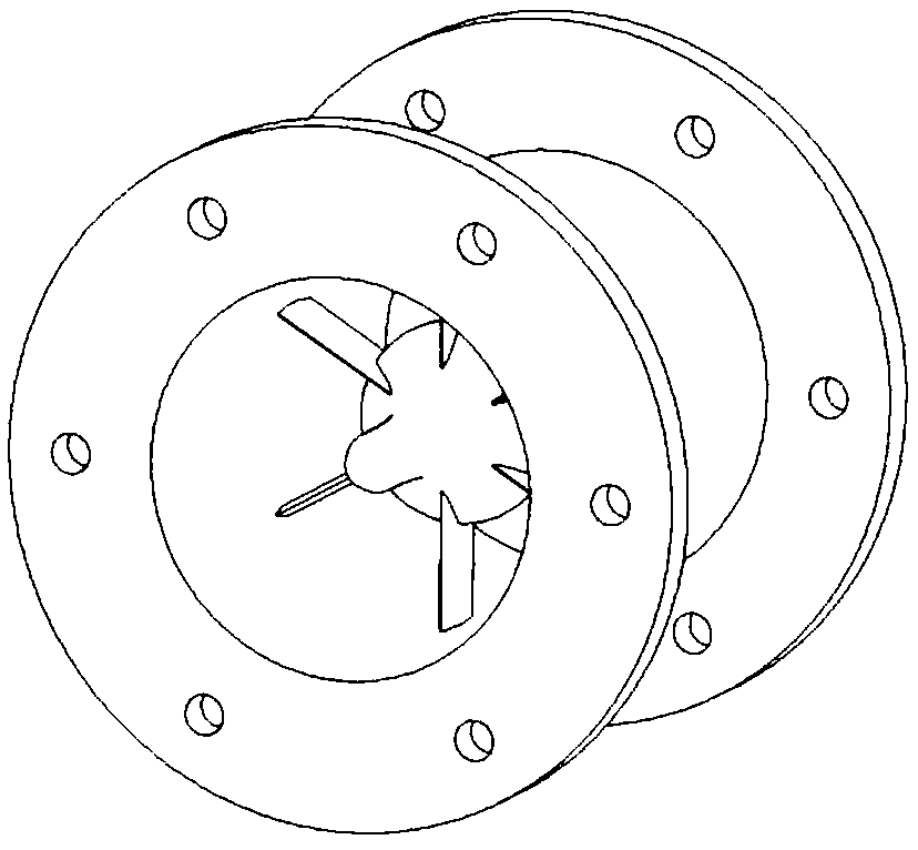
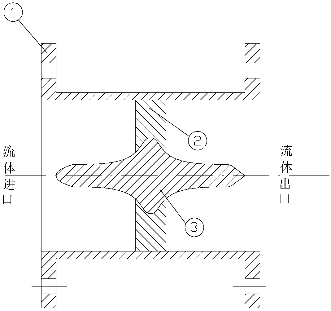
[0020] A flow field uniform device designed based on a contraction curve, the flow field uniform device includes a sleeve 1, a blade 2 and a curved contraction body 3;

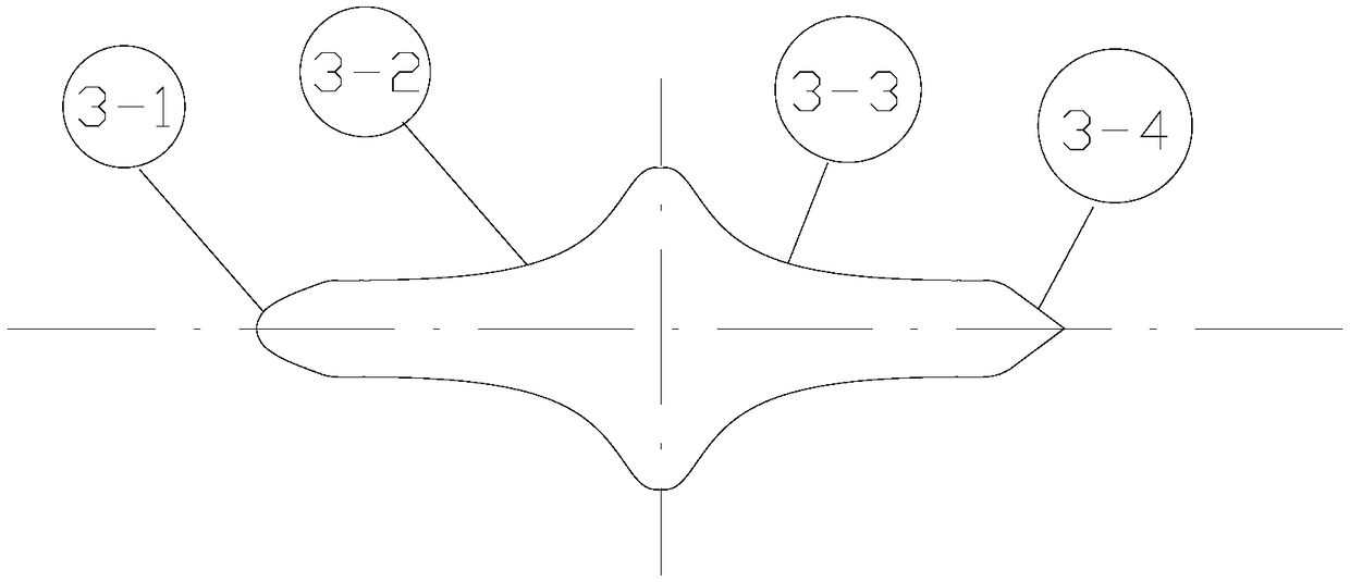
[0021] The blade 2 is designed as a symmetrical NACA blade shape with equal thickness; the curved constriction body 3 is divided into a front diversion section 3-1, a front constriction section 3-2, a rear constriction section 3-3 and a rear diversion section 3- 4 four parts; the shape of the front diversion section 3-1 is blade-shaped, and the shape of the rear diversion section 3-4 is linear; the material of the casing 1, the blade 2 and the curved shrinkage body 3 is stainless steel; the front shrinkage section 3 The profile line of -2 and the profile line of the rear contraction section 3-3 are axisymmetric and are optimized bicubic curves;

[0022] The curved contraction ...


PUM


Abstract

The invention relates to a flow field uniformizing device designed based on a contraction curve and belongs to the field of vibration noise control of liquid-filled pipelines. The flow field uniformizing device comprises a sleeve, a blade and a curve contraction body, wherein the curve contraction body is arranged inside the sleeve; the root of the blade is fixedly connected with the curve contraction body, and the tip of the blade is fixedly connected with the sleeve. The flow field uniformizing device provided by the invention is designed based on the flow channel contraction and expansion curve and achieves the purpose of rectifying fluid in the axial direction; with the adoption of a circumferential blade diversion cutting design, the effect of performing flow passage division on the fluid in the circumferential direction is achieved, and the purpose of rectifying and uniformizing a turbulent flow field within a limited length is ultimately achieved; the flow field uniformizing device is compact in structure, low in demand on mounting space and suitable for being mounted at the pump inlet end with poorer inlet flow state and at the downstream of a valve and is used for improving the speed and the pressure uniformity of the flow field and reducing the vibration noise of the pump and the valve.

Description

technical field [0001] The invention relates to a flow field uniform device designed based on shrinkage curves and using blades, belonging to the field of vibration and noise control of liquid-filled pipelines. Background technique [0002] Generally speaking, the interior space of the engine room and other cabins of large ships is limited, and there is not enough space to arrange straight pipe sections for rectification at the pump inlet and valve outlet positions, and the excessively rapid system pipeline direction will directly affect the inflow status of water pumps and other equipment, resulting in The inlet velocity field of the flow channel at the inlet part of the impeller is distorted. According to the fluid inlet velocity triangle of the turbomachinery, too small or too large inlet velocity angle will cause the fluid to separate at the impeller blades. The shaft frequency and blade frequency noise of the pump are greatly increased. Long-term operation of the equi...

Claims


Application Information

Patent Timeline
Patent Type & Authority Patents(China)
IPC IPC(8): F04D29/40F04D29/66F16K47/08
CPCF04D29/406F04D29/669F05D2240/12F05D2260/96F16K47/08
Inventor 刘海建姚伍平徐俊鲁民月苏胜利周福昌王强勇
Owner NO 719 RES INST CHINA SHIPBUILDING IND
Why Eureka
Try Eureka