Composite carbon fiber oil cylinder capable of realizing oil supply by cylinder bottom and cylinder cover

A composite carbon fiber and cylinder head technology, applied in the field of hydraulic cylinders, can solve problems such as dimensional accuracy and roughness not meeting the design requirements, peeling off of the metal lining and carbon fiber cylinder, inconsistent expansion coefficients, etc., achieving significant weight reduction effects, Solve the effect of weak connection strength and inconsistent expansion coefficient

Inactive Publication Date: 2016-10-12
CHANGZHI QINGHUA MACHINERY FACTORY +1
View PDF7 Cites 1 Cited by
  • Summary
  • Abstract
  • Description
  • Claims
  • Application Information

AI Technical Summary

Problems solved by technology

The original technology is a carbon fiber cylinder without lining. In the process of composite carbon fiber winding, the control of the deformation of the inner hole of the cylinder and the dimensional accuracy and roughness of the inner hole after winding cannot meet the design requirements, and cannot withstand high pressure; when After the metal lining is added to the inner hole of the carbon fiber cylinder, when the cylinder is under high pressure, the expansion coefficients of the metal lining and the non-metallic carbon fiber cylinder are inconsistent

Method used


Image

  • Composite carbon fiber oil cylinder capable of realizing oil supply by cylinder bottom and cylinder cover
  • Composite carbon fiber oil cylinder capable of realizing oil supply by cylinder bottom and cylinder cover

Examples


Embodiment 1

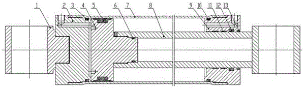
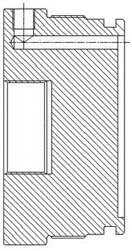
[0023] Such as figure 1 , figure 2 As shown, the composite carbon fiber cylinder with oil through the cylinder bottom and the cylinder head includes a cylinder bottom 2, a piston 4, a piston rod 8, a cylinder barrel 7 and a cylinder head 9 without metal lining, and the cylinder bottom 2 is connected to the cylinder barrel 7 There is a static seal 3 at the bottom of the cylinder, and the cylinder head 9 is sequentially provided with a dust-proof ring 13, a guide belt 11, and a static seal 10 for the cylinder head from the outside to the inside. The dust-proof ring 13 and the guide belt 11 are arranged between the piston rod 8 and the cylinder Between the covers 9, the static seal 10 of the cylinder head is arranged between the cylinder head 9 and the cylinder barrel 7, and a piston rod sealing ring 12 is also arranged between the piston rod 8 and the cylinder head 9, and the piston 4 is provided with a piston A sealing ring 5, a piston static seal 6 is arranged between the pi...

Embodiment 2

[0032] Such as figure 1 , figure 2 As shown, the composite carbon fiber cylinder with oil through the cylinder bottom and the cylinder head includes a cylinder bottom 2, a piston 4, a piston rod 8, a cylinder barrel 7 and a cylinder head 9 without metal lining, and the cylinder bottom 2 is connected to the cylinder barrel 7 There is a static seal 3 at the bottom of the cylinder, and the cylinder head 9 is sequentially provided with a dust-proof ring 13, a guide belt 11, and a static seal 10 for the cylinder head from the outside to the inside. The dust-proof ring 13 and the guide belt 11 are arranged between the piston rod 8 and the cylinder Between the covers 9, the static seal 10 of the cylinder head is arranged between the cylinder head 9 and the cylinder barrel 7, and a piston rod sealing ring 12 is also arranged between the piston rod 8 and the cylinder head 9, and the piston 4 is provided with a piston A sealing ring 5, a piston static seal 6 is arranged between the pi...


PUM

PropertyMeasurementUnit
Winding angleaaaaaaaaaa

Abstract

The invention provides a composite carbon fiber oil cylinder capable of realizing oil supply by a cylinder bottom and a cylinder cover, belongs to the technical field of hydraulic cylinders, and aims to provide a carbon fiber oil cylinder which meets the design requirement on inner bore precision, geometric tolerance and degree of finish of a cylinder barrel and works stably under high pressure. According to the technical scheme, the cylinder barrel is formed by winding composite carbon fibers and nano materials, threads which are formed by winding the composite carbon fibers and the nano materials are respectively arranged at two ends of the cylinder cover, and threads are also machined at connecting ends of the cylinder bottom, the cylinder cover and the cylinder barrel; an oil cylinder reverse cavity inlet is formed in the cylinder cover, and an oil cylinder forward cavity inlet is formed in the cylinder bottom; and the invention is applied to the carbon fiber oil cylinder.

Description

technical field [0001] The utility model relates to a composite carbon fiber oil cylinder with oil through the cylinder bottom and the cylinder head, belonging to the technical field of hydraulic oil cylinders. Background technique [0002] Lightweight design is a development direction of hydraulic cylinders. The most fundamental advantage of composite carbon fiber cylinders is that they greatly reduce the weight of components and enhance their load performance. The original technology is a carbon fiber cylinder without lining. In the process of composite carbon fiber winding, the control of the deformation of the inner hole of the cylinder and the dimensional accuracy and roughness of the inner hole after winding cannot meet the design requirements, and cannot withstand high pressure; when After the metal lining is added to the inner hole of the carbon fiber cylinder, when the cylinder is under high pressure, the expansion coefficients of the metal lining and the non-metall...

Claims


Application Information

Patent Timeline
IPC IPC(8): F15B15/14F15B15/20F16J15/16
CPCF15B15/1423F15B15/1428F15B15/1438F15B15/1447F15B15/1452F15B15/1457F15B15/1461F15B2215/30F15B2215/305
Inventor 张艳云张月红张丽娜韩晓马雷鹏周红梅于杰景小海贺胜通宋素丽
Owner CHANGZHI QINGHUA MACHINERY FACTORY
Why Eureka
Try Eureka