
Leak sensor for side detection

A sensor and sensor layer technology, applied in the field of leak sensors, can solve problems such as inability to detect leaks

Active Publication Date: 2016-10-12
FLOWNIX
View PDF10 Cites 1 Cited by
  • Summary
  • Abstract
  • Description
  • Claims
  • Application Information

AI Technical Summary

Problems solved by technology

However, in this detection method, the leak sensor should be arranged directly below the site where the leak is expected to occur, and when the leaked liquid does not fall on the upper surface of the leak sensor, there is a problem that the leak cannot be detected.
That is, a problem with the conventional area type leak sensor is that unless the leak sensor is located right at the location of the liquid leak, unless the amount of liquid that leaks and flows onto the ground is sufficient to reach the upper surface of the leak sensor, Unable to detect the occurrence of leaks

Method used


Image

  • Leak sensor for side detection
  • Leak sensor for side detection
  • Leak sensor for side detection

Examples


Embodiment Construction

[0026] Reference will now be made in detail to embodiments of the invention, examples of which are illustrated in the accompanying drawings.

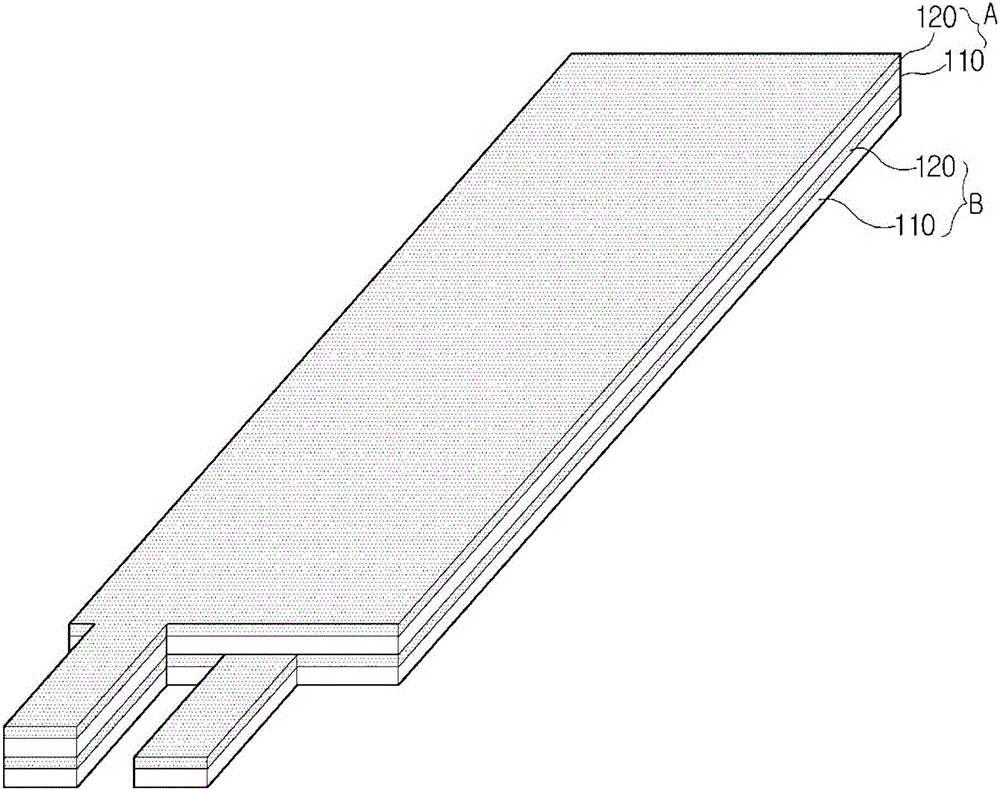
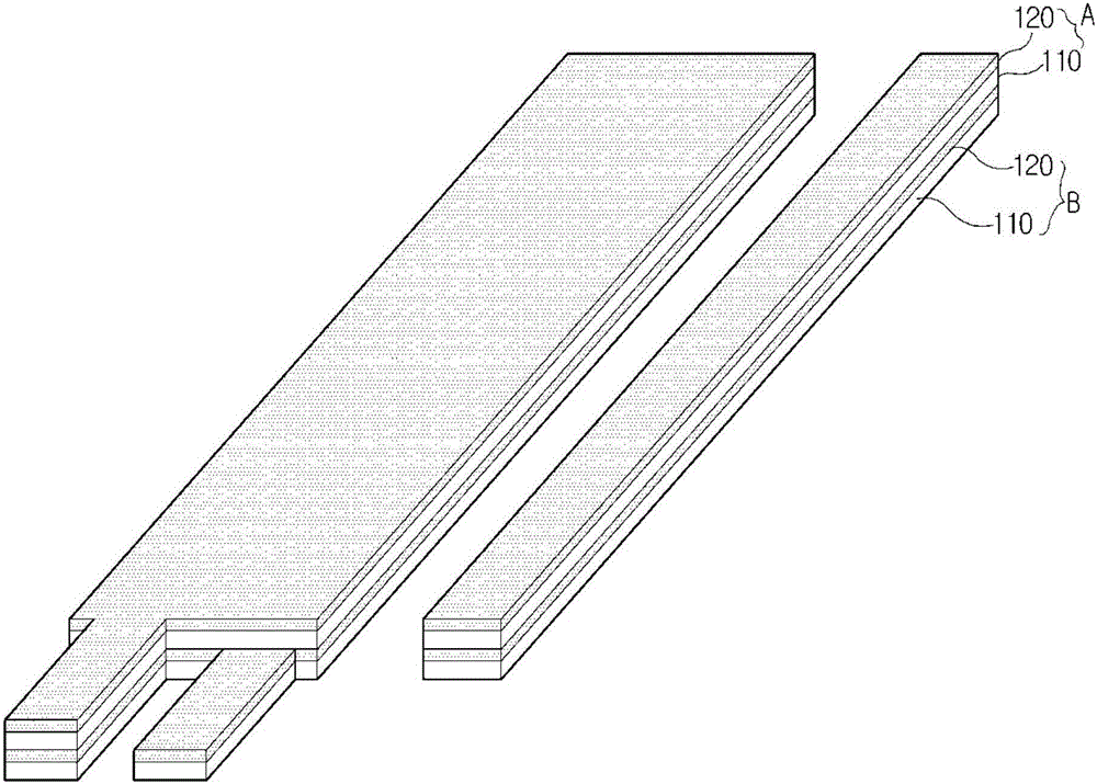
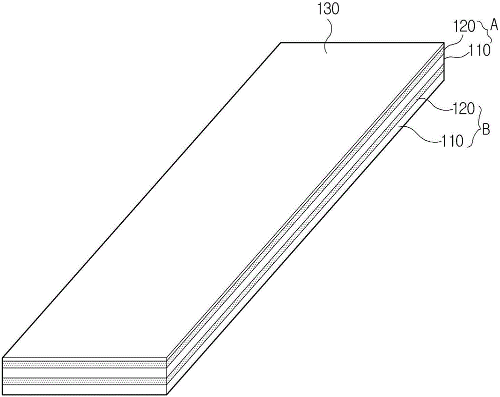
[0027] refer to figure 1 and figure 2 , The leak sensor for lateral detection according to the first embodiment of the present invention includes a base layer 110 having corrosion resistance to chemical agents and a sensor layer 120 also having corrosion resistance to chemical agents.

[0028] The base layer 110 is formed by immersing a plate-like structure in a resin solution (in particular, a fluorine-based resin solution) for a predetermined time. Here, the plate structure is a structure forming a frame of the base layer 110, and may be formed of mesh-like glass fibers. Alternatively, the base layer 110 may be formed as a plate-like structure formed of resin, particularly fluorine-based resin.

[0029] The sensor layer 120 includes a leak detection part having a predetermined area, which is formed by mixing a fluorine-based liqui...


PUM


Abstract

A leak sensor includes a base layer which is formed by soaking a plate-shaped structure into a resin solution, particularly a fluorine-based resin solution, or formed of a plate-shaped structure of a resin, particularly a fluorine-based resin; and a sensor layer in which a leak detection part having a predetermined area is formed by coating or printing a mixture of a liquid resin or a liquid fluorine-based resin and a conductive material on the base layer in a predetermined pattern, wherein the leak detection part of the sensor layer is formed on a side surface of the sensor layer to be exposed to the outside. Therefore, even though the sensor is not located just under the leaked fluid, the sensor becomes in contact with the fluid, and thus can detect the fluid leakage.

Description

technical field [0001] The present invention relates to a leak sensor capable of detecting liquid leakage through side detection, and more particularly to a leak sensor for side detection in which, even if it is not directly under the leaking liquid, it is compatible with falling and flowing into Liquid contact on the ground, and thereby detect liquid leaks. Background technique [0002] Typically, many chemicals are used in semiconductor manufacturing processes. For example, a cleaning solution, a photosensitive solution, a developing solution, and an etching solution are used in the semiconductor manufacturing process, wherein the cleaning solution is used in the cleaning operation after the cutting and polishing process of the wafer, and the photosensitive solution is used in the photosensitive process of the wafer. The developing solution is used in the developing process of the wafer, and the etching solution is used in the etching process of the wafer. [0003] These...

Claims


Application Information

Patent Timeline
IPC IPC(8): G01M3/16
CPCG01M3/16G01M3/165G01M3/18G01M3/045G01M3/04
Inventor 李在熙
Owner FLOWNIX
Learn More