
Phase measurement deflection method for aspheric surface detection

A phase measurement and aspheric technology, applied in the field of optical detection, can solve the problems of difficulty in aspheric detection, avoid approximation or calibration, facilitate operation, and improve detection accuracy.

Inactive Publication Date: 2016-10-12
SHANGHAI INST OF TECH
View PDF6 Cites 14 Cited by
  • Summary
  • Abstract
  • Description
  • Claims
  • Application Information

AI Technical Summary

Problems solved by technology

However, the incident light cannot be obtained simply and directly, and needs to be obtained by moving the display screen, calibration or approximation, which brings certain difficulties to the detection of aspheric surfaces

Method used


Image

  • Phase measurement deflection method for aspheric surface detection
  • Phase measurement deflection method for aspheric surface detection
  • Phase measurement deflection method for aspheric surface detection

Examples


Embodiment Construction

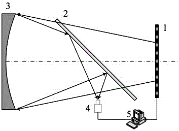
[0019] figure 1 is a schematic diagram of the detection device, wherein 1 is a liquid crystal display screen, 2 is a half mirror, 3 is a mirror to be tested, 4 is a camera, and 5 is a computer. During detection, sinusoidal stripes are generated on the liquid crystal display 1, and the sinusoidal stripes are compiled by a computer. The mirror surface of the mirror surface 3 to be tested is directly facing the liquid crystal display screen 1, that is, the connection line between the apex of the mirror surface 3 to be tested and the center of the liquid crystal display screen 1 is perpendicular to the liquid crystal display screen 1 surface, and the half-transparent mirror 2 is placed obliquely on the mirror surface 3 to be tested and Between the liquid crystal display screens 1, the light emitted from the liquid crystal display screen 1 illuminates the entire mirror surface 3 to be tested through the half mirror 2, and the light reflected by the mirror surface 3 is reflected by ...


PUM


Abstract

The invention relates to a phase measurement deflection method for aspheric surface detection. On the basis of a geometric principle of Ronchi test, a reverse optical path analysis is carried out on an improved phase measurement deflection detection method for an aspheric surface so as to obtain a deviation gradient of a to-be-detected mirror surface relative to an ideal surface shape; and integrating processing is carried out on the gradient to recover the deviation of the to-be-detected mirror surface and thus the to-be-detected mirror surface is reconstructed, so that non-contact full-field detection is carried out on the aspheric surface. With the method, a problem that incident light is obtained by display screen moving, calibration or approximation during the existing phase measurement deflection process or Ronchi testing and thus aspheric surface detection becomes inconvenient.

Description

technical field [0001] The invention relates to an optical detection technology, in particular to a phase measurement deflection method for detecting an aspheric surface. Background technique [0002] Aspherical mirror optical components have the advantages of improving imaging quality, reducing the number and weight of optical components in the system, and are widely used in various optical systems. However, the wide application of aspheric mirrors is restricted by processing technology and detection methods. In the manufacturing process of aspheric mirrors, different processing stages have different requirements for surface shape accuracy, and it is difficult to have a detection method that has the advantages of high detection accuracy, convenient use, good versatility, and low cost to apply to the processing of aspheric mirrors Therefore, it is necessary to form a complete set of diversified detection schemes to adapt to the detection requirements of different processing...

Claims


Application Information

Patent Timeline
IPC IPC(8): G01M11/00G01B11/25
CPCG01M11/00G01B11/2513
Inventor 郭春凤林晓艳邹军居家奇
Owner SHANGHAI INST OF TECH
Learn More