Matrix type mixed constant-speed sampling device

A sampling device and matrix technology, which is applied in the field of on-line monitoring devices for solid particles or gaseous pollutants, can solve the problems of narrow space, complex flue layout, and inability to represent the average concentration of flue particles or pollutants

Inactive Publication Date: 2016-10-12
NANJING YOUZHI TECH CO LTD
View PDF12 Cites 7 Cited by
  • Summary
  • Abstract
  • Description
  • Claims
  • Application Information

AI Technical Summary

Problems solved by technology

However, due to the technological and space limitations of domestic large-scale power plant boiler flue gas pipelines, the layout of the flue is complex, the space is narrow, and the straight pipe section is short, so it is difficult to achieve the measurement conditions of the straight pipe section with a uniform flow field or a relatively uniform flow field ("Stationary Pollution Sources") Determination of solid particles in exhaust gas and sampling methods of gaseous pollutants (GB / T16157-1996) requires that there should be a straight pipe length of 6 times the equivalent diameter before the sampling measurement section, and a straight pipe length of 3 times the equivalent diameter after the measurement section)
At present, almost none of the flue ducts of power plant boilers meet the sampling conditions stipulated in the above-mentioned national standards. Compared with the complex and disordered actual situation of the large-section flue flow field, the single-point sampling method has a great chance of sampling points, and the samples taken out by it Furthermore, it cannot represent the average concentration of particles or pollutants in the cross-section of the flue, resulting in large errors in the measurement data of solid particles or pollutants in the flue gas. As a legal basis for the collection of sewage charges on sewage enterprises

Method used


Image

  • Matrix type mixed constant-speed sampling device

Examples


Embodiment Construction

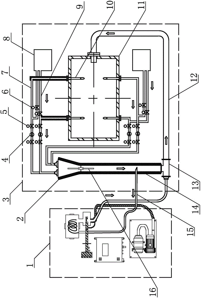
[0015] like figure 1 As shown, the matrix mixing constant velocity sampling device of the present invention includes an analysis unit 1 and a sampling unit 3, and the sampling unit 3 includes multiple sets of constant velocity circulation sampling devices. The constant velocity circulation sampling device comprises a sampling gun, and the sampling gun includes a gun body and a sampling tube 10, wherein the sampling tube 10 adopts a 316L stainless steel pipe with a diameter of 25 mm and a thickness of 2 mm, and the mouth of the sampling tube 10 is located inside the flue 11, and the sampling tube 10 Pitot tube speed measuring device (not shown in the figure) is arranged on the outside. The orifices of the plurality of sampling pipes 10 are evenly distributed around the same cross-section inside the flue 11, and the orifices face the direction of the incoming wind. According to the requirements of 4.2.4.2 of "Measurement of Solid Particulate Matter in Exhaust from Stationary Po...


PUM

PropertyMeasurementUnit
diameteraaaaaaaaaa
thicknessaaaaaaaaaa

Abstract

The invention provides a matrix type mixed constant-speed sampling device, relates to an online monitoring device for solid particulates or gaseous pollutants in exhaust gas of electric power, petroleum and chemical industry and aims to provide a matrix type mixed constant-speed sampling device which is objective and accurate in sampling and convenient to use. The matrix type mixed constant-speed sampling device comprises an analysis unit and a sampling unit, wherein the sampling unit comprises a constant-speed circular sampling device; the constant-speed circular sampling device comprises a sampling gun; orifices of sampling pipe of the sampling gun are located in a flue; pitot pipe speed measurement devices are arranged on the outer sides of the sampling pipes; a sampling pipeline is connected onto the gun body; a sampling fan is mounted on the sampling pipeline; a sampling solenoid valve is mounted at each of a gas inlet and a gas outlet of the sampling fan; the other end of the sampling pipeline is connected with an inlet joint of a mixer; the pipe diameter of a vertical pipe of the mixer is equal to the sum of the pipe diameters of the sampling pipes, and the length of the vertical pipe is equal to the sum of ten times of length of each sampling pipe; a secondary sampling pipeline is arranged at the lower part of the vertical pipe.

Description

technical field [0001] The invention relates to the technical field of monitoring solid particles or gaseous pollutants, in particular to an on-line monitoring device for solid particles or gaseous pollutants used in electric power, petroleum and chemical exhaust. Background technique [0002] At present, the sampling devices of all power plant boiler flue gas solid particles or gaseous pollutants monitoring systems use single-point sampling. The sampling method is designed for use in environments and conditions that can accurately measure The concentration of smoke particulate matter or gaseous pollutants. However, due to the technological and space limitations of domestic large-scale power plant boiler flue gas pipelines, the layout of the flue is complex, the space is narrow, and the straight pipe section is short, so it is difficult to achieve the measurement conditions of the straight pipe section with a uniform flow field or a relatively uniform flow field ("Stationary...

Claims


Application Information

Patent Timeline
Patent Type & Authority Applications(China)
IPC IPC(8): G01N1/22
CPCG01N1/2258
Inventor 李治根安建利
Owner NANJING YOUZHI TECH CO LTD
Why Eureka
Try Eureka