
Coil sensor resonance parameter measurement method and device

A coil sensor and resonance parameter technology, applied in the direction of measuring devices, measuring electrical variables, instruments, etc., can solve the problems of cumbersome operation, low reading accuracy, and affecting reliability, etc., and achieve high intelligence, high stepping accuracy, The effect of improving accuracy

Active Publication Date: 2016-10-12
HUNAN ZHONGDA CONSTR ENG TESTING TECH
View PDF6 Cites 0 Cited by
  • Summary
  • Abstract
  • Description
  • Claims
  • Application Information

AI Technical Summary

Problems solved by technology

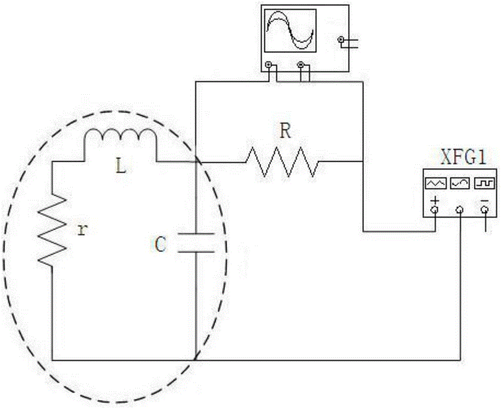
[0006] Although the resonant frequency of the coil can be measured using the above method, it still has the following disadvantages: 1. Before each measurement, the circuit must be manually tested many times to select an external resistor R with a suitable resistance value, and the operation is cumbersome. ;2. The frequency and amplitude of the output signal of the signal source (generally a function signal generator, XFG1) cannot be exactly consistent, that is, when the frequency of the signal becomes larger, its amplitude will become smaller, and the output cannot be guaranteed during the entire measurement process. The prerequisite for the constant signal amplitude, which will cause great interference to the correctness of the measurement results, unless some high-end signal sources are used, but it will lead to an increase in cost; 3. The signal source adopts the method of manual setting and reading frequency , the reading accuracy is not high; 4. The voltage value measured by the oscilloscope has a certain range limit, which cannot be fully applied to the measurement of the resonance frequency of all coils, and the resolution of the commonly used oscilloscope is only 8bit, and the reading error is large, which affects the final result. reliability

Method used


Image

  • Coil sensor resonance parameter measurement method and device
  • Coil sensor resonance parameter measurement method and device
  • Coil sensor resonance parameter measurement method and device

Examples


Embodiment Construction

[0038] The following will clearly and completely describe the technical solutions in the embodiments of the present invention with reference to the accompanying drawings in the embodiments of the present invention. Obviously, the described embodiments are only some, not all, embodiments of the present invention. Based on the embodiments of the present invention, all other embodiments obtained by persons of ordinary skill in the art without making creative efforts belong to the protection scope of the present invention.

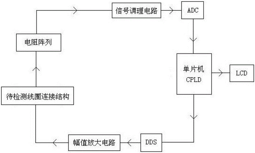
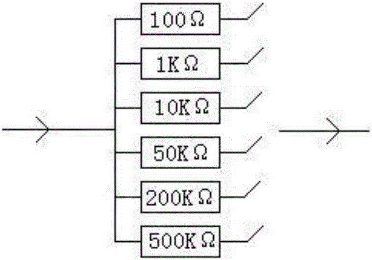
[0039] see figure 2 A device for measuring resonance parameters of a coil sensor, which includes a core component composed of a single-chip microcomputer and a CPLD, a DDS, an amplitude amplifier circuit, a connection structure of a coil to be detected, a resistance array, a signal conditioning circuit, an ADC and all components according to the transmission direction of a signal. The above-mentioned core components, and the measuring device further includes ...


PUM


Abstract

The invention provides a coil sensor resonance parameter measurement method and device. Frequency-adjustable signals generated by a DDS are controlled by a core part composed of a single-chip microcomputer and a CPLD, the amplitude of the signals is amplified to form constant-voltage signals, then the constant-voltage signals are input into a serial circuit composed of a to-be-detected coil and a resistor array, voltage signals at the two ends of series resistors are connected into an ADC through a signal conditioning circuit for data acquisition, the CPLD conducts multiple times of absolute value addition on voltage data at the same signal frequency, an average value is obtained, accordingly a stable voltage value corresponding to the signal frequency is obtained, finally the minimum voltage value is obtained by comparing stable voltage values at different signal frequencies, and signal frequency corresponding to the minimum voltage value is resonance frequency of the to-be-detected coil. The method and device are high in intelligence degree, simple in equipment structure and low in cost, and measuring precision is improved by improving frequency change precision and reducing interference.

Description

technical field [0001] The invention relates to the technical field of coil sensor measurement, in particular to a method and device for measuring resonance parameters of a coil sensor. Background technique [0002] Coil sensors are often used in transient electromagnetic methods and some near-surface frequency-domain electromagnetic instruments, which play the role of front-end inductors and signal transmitters, and the resonance parameters of the coil itself will directly affect the transmission frequency of the signal and the parasitic capacitance, The measurement and calculation of parasitic inductance requires accurate measurement of the resonance parameters of the coil. [0003] The current measurement method is to connect the coil to be tested in series with an external resistor R and the signal source, and continuously change the frequency of the output signal while keeping the output signal amplitude of the signal source unchanged, and use an oscilloscope to measure...

Claims


Application Information

Patent Timeline
IPC IPC(8): G01R35/02
CPCG01R35/02
Inventor 严发宝柳建新苏艳蕊郑翾宇赵广东
Owner HUNAN ZHONGDA CONSTR ENG TESTING TECH
Learn More