High resolution infrared imaging optical system and imaging method

An optical system and infrared imaging technology, applied in optics, optical components, instruments, etc., can solve problems such as low resolution, reduced resolution, and reduced field of view of the optical system, and achieve low resolution, easy processing, and simple structure Effect

Active Publication Date: 2016-10-12
HUBEI JIUZHIYANG INFRARED SYST CO LTD
View PDF3 Cites 4 Cited by
  • Summary
  • Abstract
  • Description
  • Claims
  • Application Information

AI Technical Summary

Problems solved by technology

However, under certain conditions, the field of view of the optical system will also decrease as the focal length increases; on the other hand, if an optical system with a very large field of view is used, the resolution of the target will inevitably be reduced. More prominent in infrared imaging systems
At present, the resolution of infrared detectors is generally much lower than that of visible light detectors. The pixel size of infrared detectors is usually above 10 μm at present, while the pixel size of visible light can reach 2 μm. Compared with visible light imaging, infrared imaging in It will be more difficult to obtain high-resolution images while ensuring a large field of view
For example, in the case of a field of view of 30 degrees, to achieve an angular resolution of 0.2mrad requires a detector resolution of about 2620*2620. Visible light detectors with this resolution are very common, but especially for infrared detectors For long-wave infrared detectors, it is still difficult to achieve stable

Method used


Image

  • High resolution infrared imaging optical system and imaging method
  • High resolution infrared imaging optical system and imaging method

Examples


Embodiment Construction

[0025] The present invention will be described in further detail below in conjunction with the accompanying drawings.

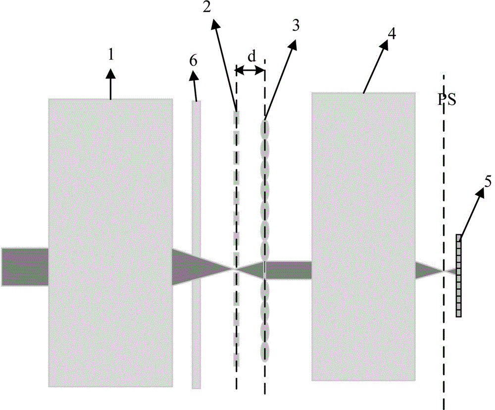
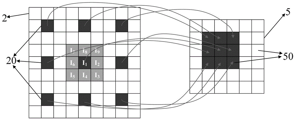
[0026] refer to figure 1 As shown, as a basic embodiment, the present invention discloses a high-resolution infrared imaging optical system, including a front optical system 1, a filter system 2, a microlens array 3, and a rear optical system sequentially arranged along the optical axis direction. The system 4 and the detector focal plane array 5, the front optical system 1 is used to collect and focus the infrared radiation radiated by the target scene. Design, its magnification and aperture angle are usually set according to the specific application range; the microlens array 3 is arranged in parallel on the rear focal plane of the front optical system 1, and the filter system 2 is a A flat lens with multiple shaded areas and transparent areas 20 is provided, the microlens array 3 is parallel to the filter system 2, the microlens array 3 is composed of a p...


PUM


Abstract

The invention discloses a high resolution infrared imaging optical system. The system comprises a front optical system, a filter system, a microlens array, a back set optical system and a detector focal plane array which are sequentially arranged along an optical axis, wherein the microlens array is arranged on a back focal plane of the front optical system, the filter system is a flat lens provided with multiple shadow areas and transparent areas, the microlens array and the filter system are parallel, the microlens array comprises multiple microlenses which are spliced together, the detector focal plane array comprises multiple image elements which are spliced together, the image elements, the microlenses and the transparent areas correspond to each other in one-to-one mode, and a modulation system is further arranged between the optical system and the filter system. The invention further discloses an imaging method. The system is advantaged in that the structure is simple, the system is easy to process, high resolution infrared imaging can be realized without any motion part, super large aperture angles can be realized, the system is particularly suitable for infrared wave bands, and a problem of low resolution of an infrared imaging system in the prior art can be effectively solved.

Description

technical field [0001] The invention belongs to the technical field of infrared optical imaging, and in particular relates to a high-resolution infrared imaging optical system and an imaging method. Background technique [0002] In many applications, it is necessary to capture high-resolution images, so that more detailed information of the target scene can be obtained. In order to obtain more target information, the usual solution is to use an optical system with a longer focal length. However, under certain conditions, the field of view of the optical system will also decrease as the focal length increases; on the other hand, if an optical system with a very large field of view is used, the resolution of the target will inevitably be reduced. It is more prominent in infrared imaging system. At present, the resolution of infrared detectors is generally much lower than that of visible light detectors. The pixel size of infrared detectors is usually above 10 μm at present, ...

Claims


Application Information

Patent Timeline
Patent Type & Authority Applications(China)
IPC IPC(8): G02B27/58
CPCG02B27/58
Inventor 张智杰郭良贤赵坤余徽孙伟岳松
Owner HUBEI JIUZHIYANG INFRARED SYST CO LTD
Why Eureka
Try Eureka