Electro-optical modulation device

An electro-optic modulation and laser technology, applied in the field of modulation, can solve the problems of insufficient speed and insufficient power, and achieve the effects of increasing the modulation rate, reducing the half-wave voltage, and efficiently coupling

Inactive Publication Date: 2016-10-12
GUILIN TRYIN TECH CO LTD
View PDF6 Cites 5 Cited by
  • Summary
  • Abstract
  • Description
  • Claims
  • Application Information

AI Technical Summary

Problems solved by technology

[0003] The invention provides an electro-optical modulation device, which solves the problems of insufficient power and insufficient speed

Method used


Image

  • Electro-optical modulation device

Examples


Embodiment Construction

[0015] The present invention will be further described with reference to the following embodiments, but the present invention is not limited to these embodiments.

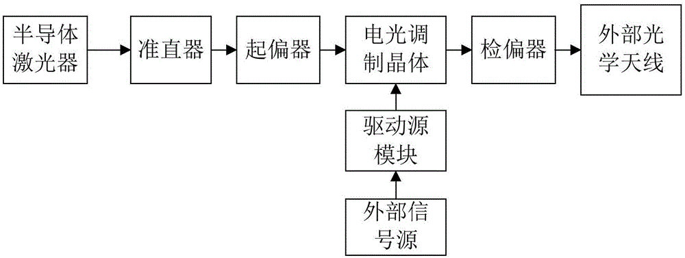
[0016] An electro-optical modulation device includes a semiconductor laser, a collimator, a polarizer, a driving source module, an electro-optical modulation crystal, and an analyzer. The output end of the semiconductor laser is connected to the input end of the collimator through an optical fiber; the output end of the collimator is connected to the input end of the polarizer; the output end of the polarizer is connected to one input of the electro-optic modulation crystal The output end of the driving source module is connected to the other input end of the electro-optic modulation crystal through a high-frequency coaxial cable; the output end of the electro-optic modulation crystal is connected to the input end of the analyzer; the analyzer The output terminal of the drive source module is connected to an external ...


PUM


Abstract

An electro-optic modulation device provided by the present invention includes a semiconductor laser, a collimator, a polarizer, a driving source module, an electro-optic modulation crystal, and a polarizer. This device is mainly aimed at the 800nm ​​band, the modulation rate is 100Mbps to 500Mbps, and the maximum optical power output is greater than 0.5w. The semiconductor laser is connected to the collimator through an optical fiber. The laser light passing through the collimator becomes polarized light after passing through the polarizer. The polarized light is modulated after passing through the electro-optic modulation crystal. Use the unit. The external signal source and the driving source module are connected with a high-frequency coaxial cable, the external signal source provides a high-frequency, high-power square wave AC signal for the driving source module, and the electro-optical modulation crystal and the driving source module are connected by a high-frequency coaxial The cable is connected, the output signal of the driving source module is sent to the electro-optic modulation crystal through the high-frequency coaxial cable and the traveling wave electrode, and the optical feedback signal of the electro-optic modulation crystal realizes the real-time control of the static working point.

Description

Technical field [0001] The invention relates to modulation technology, in particular to an electro-optical modulation device. Background technique [0002] Electro-optical modulation technology is a technology that modulates the corresponding parameters of light based on the electro-optical effect of some crystals. It is mainly used in the fields of optical communication, lithography and lidar. In space optical communication, laser is generally used as a means of information transmission, but the link distance of space laser communication is very long, and the transmission loss of laser in the atmospheric channel is very large, so the output optical power of the electro-optic modulator is required to be several hundred In the order of mw or several watts, this is something that the existing high-speed electro-optic modulation devices in optical fiber communications cannot achieve, mainly because its power is not large enough and the speed is not fast enough. Summary of the inven...

Claims


Application Information

Patent Timeline
Patent Type & Authority Applications(China)
IPC IPC(8): G02F1/03
CPCG02F1/0305
Inventor 姚峰
Owner GUILIN TRYIN TECH CO LTD
Why Eureka
Try Eureka